2.1. Command Class Overview
The following sections present a general Command Class overview and their associated rules. The requirements and recommendations apply to all Command Classes.
2.1.1. Overview
\requirement{CC:0000.00.00.11.001}{4}
The Z-Wave Plus Device Type [35], Section 7 specification indicate combinations of command classes which MUST be supported for a particular product class or type.
2.1.2. Command class format
2.1.2.1. Frame format
All commands classes have a common header consisting of a Command Class identifier and a Command identifier. Each command can have from zero to N bytes of command data. The bit numbering starts at zero for the least significant bit. LSB is denoted as ‘Bit 0’ and MSB is denoted as ‘Bit 7 throughout the document.
LSB and MSB notations are also used for multi bytes fields, indicating which byte is the most significant.
Table 2.1 and Table 2.2 below show the generic command frame for the two possible formats.
7 |
6 |
5 |
4 |
3 |
2 |
1 |
0 |
|---|---|---|---|---|---|---|---|
Command Class (0x20..0xEE) |
|||||||
Command |
|||||||
Command Data 1 |
|||||||
… |
|||||||
Command Data N |
|||||||
7 |
6 |
5 |
4 |
3 |
2 |
1 |
0 |
|---|---|---|---|---|---|---|---|
Command Class MSB (0xF1..0xFF) |
|||||||
Command Class LSB (0x00..0xFF) |
|||||||
Command |
|||||||
Command Data 1 |
|||||||
… |
|||||||
Command Data N |
|||||||
2.1.2.1.1. Command class
The Command Class identifier range is shown in Table 2.3.
Command Class |
Description |
|---|---|
0x00 |
No Operation. Used by Z-Wave Protocol. MAY be used by the application |
0x01..0x1F |
Reserved for the Z-Wave protocol |
0x20..0xFF |
Application Command Classes |
0xEF |
Support/Control mark |
0xF0 |
Non-interoperable |
0xF100 |
Security Mark |
0xF101..0xFFFF |
Extended Application Command Classes (2 byte-long Command Class identifier) |
A Command Class can contain up to 255 different Commands. If the Command Class field is in the range 0xF1..0xFF, the Command Class identifier is therefore 2 bytes long. This allows for future extensions of the Command Classes and provides the possibility of having more than 4000 Command Classes.
2.1.2.1.2. Command
The command field contains the specific command indicating a node how to parse and interpret the command data. The command field length is always 1 byte.
2.1.2.1.3. Command data (N bytes)
The command data field contains data related to the command. The description for the command data is defined in each individual command.
Simple commands, such as Get commands, usually contain no command data. Other commands, such as Set or Report commands can contain several bytes of command data.
2.1.2.2. Command class versioning
All command classes have a version number. The following rules apply to avoid interoperability issues when introducing the same Command Class with different versions:
\requirement{CC:0000.00.00.11.002}{0}
A node MUST NOT discard a frame based on the length field. A receiving node MUST use the Command Class identifier and the Command identifier to interpret the application frame. This enables a device, which supports version 1 of a Command Class to interpret the version 1 part of a received version 2 of the command.
\requirement{CC:0000.00.00.11.003}{0}
All implementations of a Command Class version higher than 1 MUST initialize all parameters associated with the version higher than 1. Thereby a node implementing the version 2 of a Command Class can interpret a version 1 received Command.
\requirement{CC:0000.00.00.11.004}{0}
A device supporting a Command Class having a version higher than 1 MUST support the Version Command Class, version 1 [OBSOLETED] to be able to identify the supported version. If a node does not support the Version Command Class, version 1 [OBSOLETED] at its highest security level, it can be assumed that all Command Classes version are equal to 1.
It is allowed to certify nodes supporting an older version of a Command Class despite a newer version exists as long as the generic/specific device specification does not require a specific version implemented.
2.1.3. Controlled and Supported Command Classes
A node can support and/or control a given Command Class.
If a Command Class is supported:
\requirement{CC:0000.00.00.11.005}{4}
The node implements all the Command Class functionalities and can be set and read back by other nodes. When a Command Class is supported, it is REQUIRED to implement the whole Command Class.
If a Command Class is controlled:
The node implements the ability to interview, read and/or set other nodes supporting the Command Class. Nodes controlling Command Classes may use only a subset of the Commands within a Command Class (for example only Set commands). Even if using a Command Class partially for control, the use must comply with the Command Class requirements.
For example, a Set Command sent to Association Group destinations is a form of Command Class control.
2.1.4. Node Information Frame
The Node Information Frame (NIF) is used to inform other devices about the node capabilities. The NIF contains a structure with a protocol specific part that is handled by the Z-Wave protocol and an application specific part that is filled in by the application. The protocol specific part consists of a bit telling if the node is a continuously listening device, the Basic Device Class the node is based on etc. The application specific part consists of the Generic and Specific Device Class and the Command Classes that are supported and/or controlled by the node.
Generic and Specific Device Class are defined in [35], Section 7 for Z-Wave Plus nodes.
A NIF will be sent to the controller when a node is to be included in the network, excluded from the network or upon request.
Table 2.4, Node Information Frame Format shows the NIF structure.
Byte descriptor / bit number |
7 |
6 |
5 |
4 |
3 |
2 |
1 |
0 |
|---|---|---|---|---|---|---|---|---|
Capability |
Listen- ing |
Routing |
Max Speed |
Protocol Version |
||||
Security |
Opt. Func. |
Sensor 1000ms |
Sensor 250ms |
Beam Capabi- lity |
Routing End Node |
Specific Device |
Contr- oller |
Secur- ity |
Reserved |
Z-Wave Protocol Specific Part |
|||||||
Basic *) |
Basic Device Class (Z-Wave Protocol Specific Part) |
|||||||
Generic |
Generic Device Class |
|||||||
Specific |
Specific Device Class |
|||||||
NodeInfo[0] |
Command Class 1 |
|||||||
… |
… |
|||||||
NodeInfo[n-1] |
Command Class N |
|||||||
*) The “Basic” field is only included when the NIF is sent by a controller
\requirement{CC:0000.00.00.11.006}{4}
The Z-Wave Protocol in a controller saves all the Node Information except the supported and controlled Command Classes when a node is included in the network. The reserved field MUST be set to 0 by a sending node and MUST be ignored by a receiving node.
2.1.4.1. Z-Wave Protocol Specific Part
The protocol specific part of the NIF is handled by the Z-Wave protocol. This information is automatically inserted in the packet by the protocol layer when transferring data using the API.
Basic Device Class
The Basic Device Class field contains an identifier that identifies what Basic Device Class this node is based on and is set by the Z-Wave protocol. A detailed description of all available Basic Device Classes is given in [35], Section 7 for Z-Wave Plus devices. The Z-Wave Plus devices have an additional parameter Role Type defining device role in the network. The Role Type parameter is announced via the Z-Wave Plus Info Command Class (Section 3).
\requirement{CC:0000.00.00.11.007}{0}
This field is only included when the NIF frame is sent by a controller. An end node MUST omit this field. Refer to [36] for controller and end node definition.
2.1.4.2. Application Specific Part
The application specific part of the NIF is handled by the application. The information must be in accordance with the defined classes to obtain interoperability.
Listening Flag
The Listening flag is used to indicate that the node is always listening if set to 1. An always listening node must be powered continuously and reside on a fixed position in the installation. An always listening node is included in the routing table to assist as repeater in the network. The routing table is static during normal operation. In case the Listening flag is set to 0, the node is non-listening. This is typically used for battery operated nodes being asleep when the protocol is idle to prolong battery lifetime. A battery operated node is not included in the routing table and is not used as a router in the network. In some instances the node’s position in the network is still determined, and stored by the protocol.
Optional Functionality Flag
The Optional Functionality flag is used to indicate that this node supports other Command Classes than the mandatory for the selected generic/specific device class and that a controlling node needs to look at the supported Command Classes to fully control this device.
Generic Device Class
The Generic Device Class field contains an identifier that identifies what Generic Device Class this node is part of and must be set by the application. For a detailed description of all available Generic Device Classes, refer to [35], Section 7 for Z-Wave Plus devices.
Specific Device Class
The Specific Device Class field specifies what Specific Device Class this application is part of and must be set by the application. For a detailed description of all available Specific Device Classes, refer to [35], Section 7 for Z-Wave Plus devices.
Command Class
\requirement{CC:0000.00.00.11.008}{0}
The Command Class field is used to advertise Command Classes implemented by the node. The field MUST NOT be longer than 35 bytes.
\requirement{CC:0000.00.00.11.009}{0}
The field MUST advertise the list of Command Classes that the node supports.
\requirement{CC:0000.00.00.13.002}{0} \requirement{CC:0000.00.00.11.00A}{4} \requirement{CC:0000.00.00.12.004}{8}
The field MAY advertise the list of Command Classes that the node can control in other nodes. If present, the list of controlling Command Classes MUST be prepended by the COMMAND_CLASS_MARK Command Class identifier. It is NOT RECOMMENDED to advertise controlled Command Classes.
\requirement{CC:0000.00.00.12.001}{4}
It has been found that legacy controllers may read as little as 6 lines from this list. For backwards compatibility, the list SHOULD advertise supported command classes in the order indicated in Table 2.5, NIF :: Command Class advertising priorities :
Priority |
Command Class |
|---|---|
1 (First line) |
COMMAND_CLASS_ZWAVEPLUS_INFO Applies only to Z-Wave Plus products |
2 (if supported) |
COMMAND_CLASS_SWITCH_MULTILEVEL or COMMAND_CLASS_SWITCH_BINARY |
3 (if supported) |
COMMAND_CLASS_SWITCH_ALL |
4 (if supported) |
COMMAND_CLASS_ASSOCIATION |
5 |
All other command classes |
Table 2.6, NIF::Command Class list structure shows the Command Class list structure of the Node Information frame:
Description |
Command Class list field content |
|||||||
|---|---|---|---|---|---|---|---|---|
7 |
6 |
5 |
4 |
3 |
2 |
1 |
0 |
|
Non-secure Supported Command Classes |
Command Class 1 *) |
|||||||
… |
||||||||
Command Class M *) |
||||||||
Support / Control Mark |
0xEF |
|||||||
Non-secure Controlled Command Classes |
Command Class 1 *) |
|||||||
… |
||||||||
Command Class K *) |
||||||||
*) Command classes may be extended -> spanning two bytes for one command class
\requirement{CC:0000.00.00.13.003}{0}
The Command Class list MAY start or finish with the identifier COMMAND_CLASS_MARK.
2.1.4.3. NIF and Multi Channel/Security Command Classes
\requirement{CC:0000.00.00.11.00B}{0}
The NIF MUST represent command classes supported without Multi Channel or Security encapsulation (Section 4).
After inclusion in a Z-Wave network, the NIF represents the node’s Command Class capabilities when using no Security and no Multi Channel encapsulation.
Multi Channel Root Devices advertise their capabilities via the NIF, but they advertise the Command Class capabilities of their End Points via the Multi Channel Command Class.
Security bootstrapped nodes advertise their capabilities using security encapsulation via the Security 0 or Security 2 Command Class.
The Command Class list advertised in the NIF may vary depending on the inclusion state and S0/S2 bootstrapping state of the node.
\requirement{CC:0000.00.00.11.00C}{0}
A node supporting security (S0 and/or S2) MUST advertise command classes in the NIF according to Table 2.7, NIF content depending on inclusion and security bootstrapping.
Network inclusion |
Security bootstrapping |
Command Classes advertised in the NIF |
|---|---|---|
Not included in a network |
N/A |
At least all Command Classes that MUST always be non securely supported. All supported Command Classes MAY be advertised |
Included in a network |
No security supported by the included node |
All supported Command Classes |
Included in a network |
Before the node times out waiting for Security bootstrapping |
At least all Command Classes that MUST always be non securely supported. All supported Command Classes MAY be advertised |
Included in a network |
Timed out waiting for Security Bootstrapping (i.e. the process never started) |
The same Command Class list as when security bootstrapping is successful but no key was granted *) |
Included in a network |
Security bootstrapping failed. (i.e. the process started but did not complete without error) |
All Command Classes that MUST always be non-securely supported Command Classes that are supported when no key is granted MAY be added or removed from the list. *) |
Included in a network |
Bootstrapped with S0/S2 |
All Command Classes that MUST always be non securely supported only. (i.e. Command Classes supported even if not using S0/S2 encapsulation). |
*) Refer to each individual Device Type [35], Section 7 for the list of Command Classes supported when no security key is granted
\requirement{CC:0000.00.00.11.00D}{0}
Command Classes advertised as supported in the NIF after S0/S2 bootstrapping MUST also be supported at higher security levels unless encapsulated outside security.
2.1.4.3.1. Examples
In the case of a node requesting Access Control, they require a certain security level before supporting their command class. For example a Door Lock Device Type will support its command classes as shown in Figure 2.1
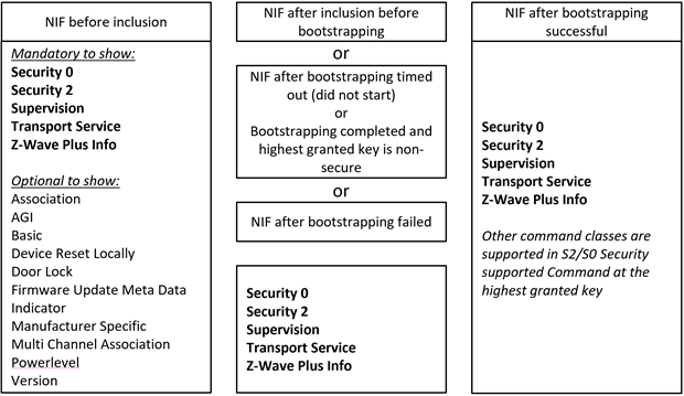
Figure 2.1 Access Control node NIF contents (always non-secure Command Classes shown in bold)
Nodes requesting a lower security level than Access Control have more freedom about advertising their regular command classes in the different scenarios. An example of a Binary Switch Device Type is shown in Figure 2.2
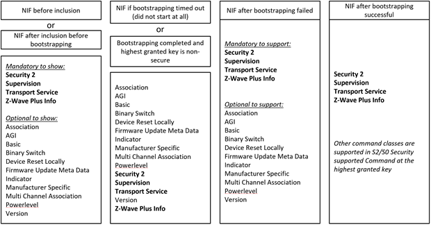
Figure 2.2 Non-Access Control node NIF contents (always non-secure Command Classes shown in bold)
2.1.4.4. Command Class specific NIF rules
\requirement{CC:0000.00.00.13.004}{0}
A given Command Class MAY have additional requirement with respects to the NIF, Multi Channel Capability Report or S0/S2 Commands Supported Report.
For example, the Basic Command Class is never advertised in the NIF or the Z-Wave Plus Info is always in the NIF if supported.
In this case, requirements are listed in each individual Command Class definition, in the compatibility considerations section.
2.1.5. Multicast and broadcast commands
\requirement{CC:0000.00.00.13.006}{0}
A node MAY send a command to several destinations using a Multicast or Broadcast frame. This is allowed only if the actual command does not require the responding node to return a response.
Unless specified otherwise for a particular command:
\requirement{CC:0000.00.00.11.00E}{4}
Commands requiring another command to be returned in response by a receiving node MUST NOT be issued via multicast addressing in a Z-Wave network
\requirement{CC:0000.00.00.11.00F}{0}
A receiving node MUST NOT return a response if a command is received via multicast addressing.
The Z-Wave Multicast frame, the broadcast NodeID and the Multi Channel multi-End Point destination are all considered multicast addressing methods.
2.1.6. Actuator Control
An actuator device may support one or more actuator command classes. This section presents terminology and conventions applying to all actuator command classes.
The actuator control group comprises the following command classes:
Barrier Operator Command Class
Basic Command Class
Binary Switch Command Class
Color Switch Command Class
Door Lock Command Class
Multilevel Switch Command Class
Simple AV Command Class
Sound Switch Command Class
Thermostat Setpoint Command Class
Thermostat Mode Command Class
Window Covering Command Class
2.1.6.1. Terminology
Actuators may be controlled in two possible manners.
A position actuator responds to a position control command, which specifies a target value and optionally a duration for the transition from the current value to the target value. The value may be binary or multilevel.
State control commands may be encoded as special multilevel position control values, e.g. 0xFF for “On” and 0x00 for “Off”. The most recent (non-zero) target value is restored in response to the “On” state control command.
A motion actuator responds to start/stop commands. A motion control command specifies a direction, optionally a start value, and a transition rate.
2.1.6.2. Reporting values
A position control command may be used to initiate a transition to a new target value. A position report advertises the current value of the device hardware, optionally the target value and the remaining transition duration. If the transition is initiated by a motion control command, the reported target value is the min or max value and the duration is the time needed to reach the target value at the actual transition rate.
A controlling device should not assume that the position value advertised in a Report is identical to a value previously issued with a position control command when a transition has ended.
\requirement{CC:0000.00.00.53.002}{0} \requirement{CC:0000.00.00.52.001}{8}
A controlling node MAY want to receive application-level acknowledgements after issuing actuating commands. It is the responsibility and choice of the controlling node whether or not to ensure that a actuating command has been successfully executed. If doing so, it is RECOMMENDED to use the Supervision Command Class, version 1 or MAY read back the node’s state at a later time with a Get Command.
\requirement{CC:0000.00.00.12.005}{0}
A supporting node receiving an actuating Command SHOULD NOT return a Report Command advertising its status or level unless specified in the Command Class specification.
2.1.6.3. Command values vs. hardware values
\requirement{CC:0000.00.00.11.010}{8}
A device may implement fewer hardware levels than supported by a position control Command Class. The hardware levels should be distributed uniformly over the entire range. The mapping of command values to hardware levels must be monotonous, i.e. a higher value MUST be mapped to either the same or a higher hardware level. An example is found in Table 2.8, Mapping command values to hardware levels (example).
Multilevel Value |
Hardware level |
State |
|---|---|---|
0 |
0 |
Off |
1..33 |
33% |
On |
34..66 |
66% |
On |
67..99 |
100% |
On |
2.1.6.4. Supporting multiple actuator Command Classes
\requirement{CC:0000.00.00.13.007}{0} \requirement{CC:0000.00.00.13.008}{4}
Several actuator Command Classes MAY co-exist in a node or Multi Channel End Point. For example, a node MAY support both Window Covering Command Class and Multilevel Switch Command Class.
\requirement{CC:0000.00.00.12.002}{0} \requirement{CC:0000.00.00.12.003}{4}
In this case, the two actuator Command Classes SHOULD actuate the same resource. If a node implements several actuating resources, e.g. a LED and a power switch, it is RECOMMENDED to use Multi Channel End Points for each individual resource.
2.1.7. Common fields and encoding
2.1.7.1. Reserved and Res fields
\requirement{CC:0000.00.00.11.011}{0}
Fields named ‘Reserved’ or ‘Res’ MUST be set to 0 by a sending node and MUST be ignored by a receiving node.
2.1.7.2. Reserved values and reserved bits
\requirement{CC:0000.00.00.11.012}{0}
Values of fields in commands that are marked as “reserved” or “res” MUST NOT be used by devices sending commands and MUST be ignored by devices receiving commands.
\requirement{CC:0000.00.00.11.013}{0}
Bits in commands that are marked as “reserved” or “res” MUST be set to 0 by devices sending commands and MUST be ignored by devices receiving commands.
\requirement{CC:0000.00.00.11.014}{0}
Undefined values for a given parameter MUST be treated as “reserved”. Reserved values MUST NOT be used by a sending node and MUST be ignored by a receiving node.
2.1.7.3. Duration encoding
\requirement{CC:0000.00.00.11.015}{4}
Some actuator command classes allow controlling nodes to specify a duration for reaching the target value. The duration MUST be encoded according to Table 2.9, Actuator Command Class Duration Set encoding.
Value |
Description |
|---|---|
0x00 |
Instantly |
0x01..0x7F |
1 second (0x01) to 127 seconds (0x7F) in 1 second resolution. |
0x80..0xFE |
1 minute (0x80) to 127 minutes (0xFE) in 1 minute resolution. |
0xFF |
Factory default duration. |
\requirement{CC:0000.00.00.11.016}{4}
A node supporting an actuator Command Class may advertise the duration left to reach the target value advertised in a report. The duration MUST be encoded according to Table 2.10, Actuator Command Class Duration Report encoding.
Value |
Description |
|---|---|
0x00 |
0 seconds. Already at the Target Value. |
0x01..0x7F |
1 second (0x01) to 127 seconds (0x7F) in 1 second resolution. |
0x80..0xFD |
1 minute (0x80) to 126 minutes (0xFD) in 1 minute resolution. |
0xFE |
Unknown duration |
0xFF |
Reserved |
2.1.7.4. Unsigned encoding
\requirement{CC:0000.00.00.11.017}{4}
Unless specified otherwise in a field description, the field encoding is using unsigned representation. Fields using unsigned encoding MUST comply with Table 2.11, Default unsigned encoding examples
Value (hex) |
unsigned 8-bit representation (decimal) |
Value (hex) |
Unsigned 16-bit representation (decimal) |
Value (hex) |
Unsigned 32-bit representation (decimal) |
||
|---|---|---|---|---|---|---|---|
0x00 |
0 |
0x0000 |
0 |
0x00000000 |
0 |
||
0x01 |
1 |
0x0001 |
1 |
0x00000001 |
1 |
||
0x02 |
2 |
0x0002 |
2 |
0x00000002 |
2 |
||
0x7F |
127 |
0x7FFF |
32767 |
0x7FFFFFFF |
2147483647 |
||
0x80 |
128 |
0x8000 |
32768 |
0x80000000 |
2147483648 |
||
0xFE |
254 |
0xFFFE |
65534 |
0xFFFFFFFE |
4294967294 |
||
0xFF |
255 |
0xFFFF |
65535 |
0xFFFFFFFF |
4294967295 |
2.1.7.5. Signed encoding
Some fields use the signed encoding representation.Signed encoding is using the representation. Fields using signed encoding MUST comply with Table 2.12.
Value |
Signed 8-bit representation |
Value |
Signed 16-bit representation |
Value |
Signed 32-bit representation |
||
|---|---|---|---|---|---|---|---|
0x7F |
127 |
0x7FFF |
32767 |
0x7FFFFFFF |
2147483647 |
||
0x02 |
2 |
0x0002 |
2 |
0x00000002 |
2 |
||
0x01 |
1 |
0x0001 |
1 |
0x00000001 |
1 |
||
0x00 |
0 |
0x0000 |
0 |
0x00000000 |
0 |
||
0xFF |
-1 |
0xFFFF |
-1 |
0xFFFFFFFF |
-1 |
||
0xFE |
-2 |
0xFFFE |
-2 |
0xFFFFFFFE |
-2 |
||
0x80 |
-128 |
0x8000 |
-32768 |
0x80000000 |
-2147483648 |
2.1.7.6. Fields values and version
\requirement{CC:0000.00.00.11.019}{4}
New Command Class versions may define new possible values for a field introduced previously. In that case, a version column is added to the value table. A supporting node MUST support the values associated its version and previous versions and MUST NOT support values associated to future versions. An example is given in Table 2.13 Field values and Command Class version (example).
Value |
Description |
Version |
|---|---|---|
0x00 |
Value introduced in version 1, valid and mandatory in all versions |
1 |
0x01 |
Value introduced in version 2, valid and mandatory in version 2 and newer. Version 1 MUST consider this value as reserved |
2 |
0x02 |
Value introduced in version 2, valid and mandatory in version 2 and newer. Version 1 MUST consider this value as reserved |
2 |
0xFF |
Value introduced in version 3, valid and mandatory in version 3 and newer. Version 1 and 2 MUST consider this value as reserved |
3 |