4.2.5. Security 0 (S0) Command Class, version 1
The Security Command Class create the foundation for secure application communication between nodes in a Z-Wave network. The security layer provides confidentiality, authentication and replay attack robustness through AES-128.
The Security Command Class defines a number of commands used to facilitate handling of encrypted frames in a Z-Wave Network. The commands deal with three main areas:
Message Encapsulation. The task of taking a plain text frame and encapsulating the frame into an encrypted Security Message.
Command Class Handling. The task of handling what command classes are supported when communicating with a Security enabled device
Network Key Management. The task of initial key distribution.
4.2.5.1. Compatibility considerations
A node supporting the S0 Command Class MAY use the S2 CTR_DRBG as a PRNG.
A node supporting the S0 Command Class MUST NOT allow S0 bootstrapping after a failed S2 bootstrapping initiated by the controller.
4.2.5.1.1. Node Information Frame (NIF)
A supporting node MUST advertise the Security 0 Command Class in its NIF before inclusion.
A supporting node MUST advertise the Security 0 Command Class in its NIF after successful S0 security bootstrapping.
A supporting node MAY advertise the Security 0 Command Class in its NIF after inclusion without Security bootstrapping.
A supporting node MUST NOT advertise the Security 0 Command Class in its S0/S2 Commands Supported Report list.
4.2.5.2. Message Encapsulation and Command Class Handling
For encapsulating messages, Z-Wave requires four commands. Before sending an encrypted frame, the sender MUST request a nonce (number used once) from the recipient. The sender subsequently uses this number along with the locally generated nonce and the network key to generate the Security Message Encapsulation Command as illustrated in Figure 4.3.
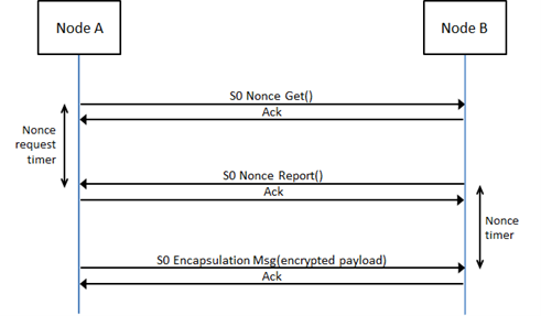
Figure 4.3 Sending secure messages
This mechanism generates an overhead of three commands for each single frame that is sent encrypted (plus acknowledge frames).
A number of timers have to be implemented in order to mitigate attacks.
A timer denoted Nonce request timer in Figure 4.3 and Figure 4.4 SHOULD be started by a node sending a Nonce Get Command. If the Nonce request timer is started, the Nonce Report MUST be received before the timer runs out. The duration of this timer will depend on the application it is trying to protect.
A timer denoted Nonce timer in Figure 4.3 and Figure 4.4 MUST be started by a node after sending a Nonce Report Command. The S0 Encapsulated Message MUST be received within the specified timeout in order to be accepted.
The Nonce timer MUST implement a timeout in the range 3..20 seconds.
Note that the Nonce timer and the Nonce request timer MUST be started when the command has been sent and not when the transmission has been acknowledged, since an attacker could delay the acknowledgement frame.
Both timers MUST be used in all communication that uses the mentioned commands.
In order to optimize the performance the device MUST use streaming when transmitting multiple frames. The overhead using this option will converge towards two (instead of three) transmissions as the number of frames increases.
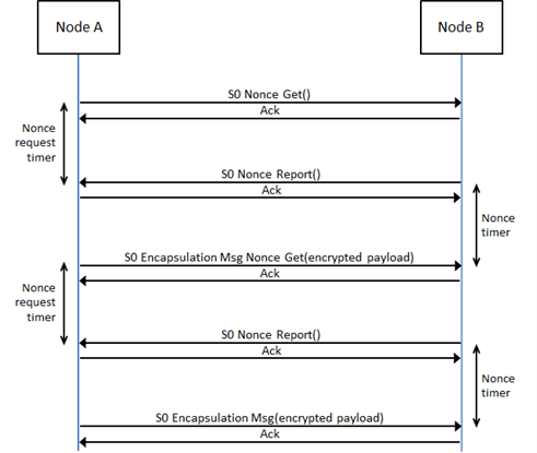
Figure 4.4 Streaming secure messages
Notice: The maximum command size is reduced by 20 bytes due to the security encapsulation command overhead. Larger commands can use sequencing as described in Section 4.2.5.2.2.
4.2.5.2.1. Nonce Get Command
This command is used to request an external nonce from the receiving node.
Note that a nonce will only be valid for one encrypted command attempt. The nonce is discarded when the receiver has used it for decrypting the next received command. A new nonce MUST be exchanged for each new command.
The Nonce Report Command MUST be returned in response to this command.
This command MUST NOT be issued via multicast addressing.
A receiving node MUST NOT return a response if this command is received via multicast addressing. The Z-Wave Multicast frame, the broadcast NodeID and the Multi Channel multi-End Point destination are all considered multicast addressing methods.
7 |
6 |
5 |
4 |
3 |
2 |
1 |
0 |
|---|---|---|---|---|---|---|---|
Command Class = COMMAND_CLASS_SECURITY (0x98) |
|||||||
Security Header = SECURITY_NONCE_GET (0x40) |
|||||||
4.2.5.2.2. Nonce Report Command
This command is used to return the next nonce to the requesting node.
7 |
6 |
5 |
4 |
3 |
2 |
1 |
0 |
|---|---|---|---|---|---|---|---|
Command Class = COMMAND_CLASS_SECURITY (0x98) |
|||||||
Security Header = SECURITY_NONCE_REPORT (0x80) |
|||||||
Nonce Byte 1 |
|||||||
Nonce Byte 2 |
|||||||
Nonce Byte 3 |
|||||||
Nonce Byte 4 |
|||||||
Nonce Byte 5 |
|||||||
Nonce Byte 6 |
|||||||
Nonce Byte 7 |
|||||||
Nonce Byte 8 |
|||||||
Nonce byte (8 bytes)
This field contains the 8 bytes external nonce used for encryption, generated with the PNRG by the sending node.
4.2.5.2.3. Security Message Encapsulation Command
The device uses the Security Message Encapsulation command to encapsulate Z-Wave commands using AES-128.
A sending node is also requesting a new nonce from the receiving node when transmitting the Security Message Encapsulation Nonce Get Command. The sending node uses the new nonce when streaming multiple secure messages without having to send a separate Nonce Get Command after sending each command as shown in Figure 4.4, Streaming secure messages.
A device MUST ignore the received Security Message Encapsulation Command if the generated Nonce has timed out.
7 |
6 |
5 |
4 |
3 |
2 |
1 |
0 |
|---|---|---|---|---|---|---|---|
Command Class = COMMAND_CLASS_SECURITY (0x98) |
|||||||
Security Header = SECURITY_MESSAGE_ENCAPSULATION (_NONCE_GET) (0x81/0xC1) |
|||||||
Initialization Vector Byte 1 |
|||||||
Initialization Vector Byte 2 |
|||||||
Initialization Vector Byte 3 |
|||||||
Initialization Vector Byte 4 |
|||||||
Initialization Vector Byte 5 |
|||||||
Initialization Vector Byte 6 |
|||||||
Initialization Vector Byte 7 |
|||||||
Initialization Vector Byte 8 |
|||||||
Reserved |
Second Frame |
Sequenced |
Sequence Counter |
||||
(Command Class identifier) |
|||||||
(Command identifier) |
|||||||
Command byte 1 |
|||||||
… |
|||||||
Command byte N |
|||||||
Receiver’s nonce Identifier |
|||||||
Message Authentication Code byte 1 |
|||||||
Message Authentication Code byte 2 |
|||||||
Message Authentication Code byte 3 |
|||||||
Message Authentication Code byte 4 |
|||||||
Message Authentication Code byte 5 |
|||||||
Message Authentication Code byte 6 |
|||||||
Message Authentication Code byte 7 |
|||||||
Message Authentication Code byte 8 |
|||||||
Initialization Vector byte (8 byte)
The initialization vector is the internal nonce generated by the sender. The payload is encrypted with the external and internal nonce concatenated together.
Reserved
This field MUST be set to 0 by a sending node and MUST be ignored by a receiving node.
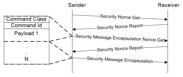
Figure 4.5 Frame flow for sequenced frames
Sequenced (1 bit) (Part of Encrypted Payload)
This flag MUST be set if the command is transmitted using multiple frames. This flag MUST not set if the command is contained entirely in a single (this) frame. As shown in figure, the first frame in a sequence MUST be sent using Security Message Encapsulation Nonce Get. To minimize overhead, following frames SHOULD be sent using the Security Message Encapsulation Nonce Get command. The last frame MAY be sent using Security Message Encapsulation.
Second Frame (1 bit) (Part of Encrypted Payload)
If this flag and the Sequenced flag are set, the frame is the second out of two. If the flag is not set, and Sequenced flag is set, it is the first frame out of two. Valid combinations are:
Sequenced 1 |
Sequenced 0 |
|
|---|---|---|
Second Frame 1 |
Second frame of two |
- |
Second Frame 0 |
First frame of two |
Single Frame |
Sequence Counter (4 bits) (Part of Encrypted Payload)
If Sequenced flag is set, the frame is one out of two. In order to tell multiple sequences apart, they MUST be uniquely identified based on the sender NodeID and the Sequence Counter. For each sequenced set of frames a node sends it MUST increment the Sequence Counter by one.
Command Class Identifier (8 bits) (Part of Encrypted Payload)
This field contains the identifier of the Command class, which the device sends to the NodeID.
Command identifier (8 bits) (Part of Encrypted Payload)
This field contains the identifier of the Command, which the device sends to the NodeID.
Command byte (N bytes) (Part of Encrypted Payload)
These fields contain the parameters, which the device sends to the NodeID.
Receiver’s nonce Identifier (8 bits)
Identifies nonce being used.
Message Authentication Code byte (8 bytes)
Data used for authenticating the received message to prevent tampering.
4.2.5.3. Network Key Management
The same network key is used by all secure nodes in the network. Distribution of network keys uses a temporary key to protect the key exchange. Exchange of network key happens immediately after successful inclusion of the node. It requires a secure primary/inclusion controller to include a secure node into the secure network as secure.
4.2.5.3.1. Network inclusion
The first step of including a node to a secure network is using the standard Z-Wave inclusion process. If both the new node and the inclusion controller support Security command class, the controller will subsequently send the network key to the newly included node.
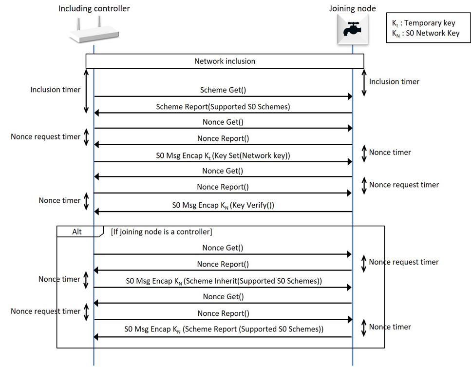
Figure 4.6 Inclusion into a secure network
To protect the security of a secure network, all controllers SHOULD require a PIN to unlock the security inclusion process and end nodes SHOULD require a PIN to accept being included and excluded.
Following the inclusion of the node into the network, the controller will request the security scheme supported by the included node. Battery operated devices SHOULD stay awake for the duration of the setup of the Security Command class.
Currently one security scheme exist which is extendable at a later stage:
Security 0/N: 0x00 repeated 16 times as temporary key for encrypting the network key when it is transferred using normal power.
The validity of the key is verified in both the added node and the including controller. The node verifies the key based on the Message Authentication Code and then transmits an encrypted Network Key Verify command as response to the controller. When a device supporting the Security Command class does not manage to enter the secure network, it will function as a non-secure device. The node requires exclusion from the network before another attempt comprising of inclusion and network key exchange is possible.
For the currently available Security 0/N scheme, the same network key is used by all nodes in the network.
For the including controller to allow S0 bootstrapping into the secure network, a common security scheme needs to be supported by both nodes. When supporting multiple common schemes, the highest possible scheme MUST be used. If no common schemes are supported the node MUST NOT be S0 bootstrapped.
When controller nodes in the secure network wish to establish a connection to a node that supports the Security 0 Command class, they MUST send the Security 0 Command Supported Get Command to the node. Receiving no Security Command Supported Report (since the receiving node does not have the key to decrypt the request), means that it will not be able to talk to this node securely. The same applies for the situation where a secure node does not become part of the secure network because it was included by a non-secure controller.
A node based on a end node Role Type MUST NOT consider a secure inclusion successful until the Network Key Set has been received.
A node based on a controller Role Type MUST NOT consider the secure inclusion successful until the Security Scheme Inherit Command has been received.
4.2.5.3.1.1. Inclusion through Non-Secure Inclusion controller
A Security-enabled SIS MAY perform secure setup after inclusion from a non-secure inclusion controller. As soon as the Security enabled SIS (hereafter SIS), receives information from the non-secure inclusion controller that a node with support for the Security command class has been included, the SIS MAY start the secure setup process of sending the network key to the newly included node as illustrated in Figure 4.7. At this stage the SIS acts as if it, itself had performed the inclusion and MAY carry out all the steps REQUIRED for secure setup, included making sure the timeouts are not exceeded.
Before starting the Secure inclusion process, the SIS MUST be put into a state that allows it to carry out the secure setup for 1 node for the next 3 minutes and no longer. The SIS MUST be put in this state through a password-protected menu to avoid unintentional reveal of the network key by a fake controller.
It should be noted that performing the secure setup on behalf of a non-secure inclusion controller might add to the complexity of the actions required by the user, and thus make it easier for a hacker to perform social engineering to circumvent the security so care must be taken to inform the user accordingly.
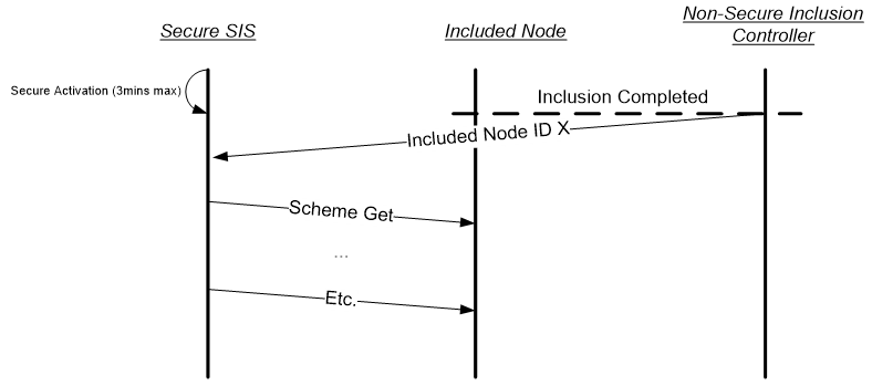
Figure 4.7 Secure Inclusion through Non-Secure Inclusion Controller
4.2.5.3.1.2. Inclusion Timers
As shown in Figure 4.6, a number of timeout MUST be complied with. For the including controller see Figure 4.8.
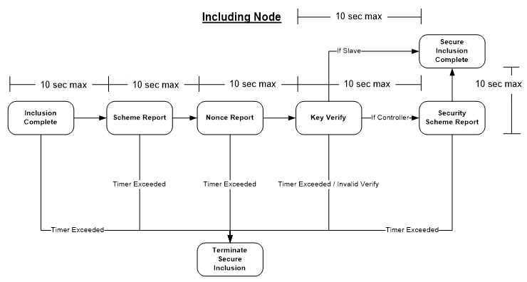
Figure 4.8 Timers on Including Controller
For the new included node, the timers in Figure 4.9 MUST be complied with.
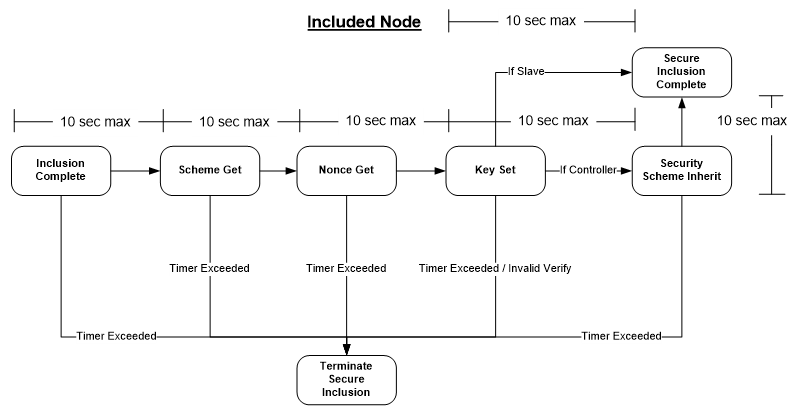
Figure 4.9 Timers on newly Included Node
The Network Key MUST NOT be sent to the new node if a Security Scheme Report Command is received by the including controller later than 10 seconds after successful inclusion of the node. The controller SHOULD notify the user of an error condition in case of timeout because the device functions only as non-secure. In addition, the included node MUST NOT accept and respond to a Scheme Get it is received later than 10 seconds after network inclusion. When a valid frame is received before the timeout, the timeout is extended to allow the next part of the inclusion process. The S0 bootstrapping process MUST be terminated if any message times out.
4.2.5.3.2. Security Scheme Get Command
A controlling device MUST send Security Scheme Get Command immediately after the successful inclusion of a node that supports the Security Command class.
A node is considered newly included if it has been included for less than 10 seconds.
A newly included node MUST return the Security Scheme Report Command in response to this command.
Whether a node has been included securely or non-securely, the node MUST NOT respond to the Security Scheme Get command if it is not newly included.
This command MUST NOT be issued via multicast addressing.
A receiving node MUST NOT return a response if this command is received via multicast addressing. The Z-Wave Multicast frame, the broadcast NodeID and the Multi Channel multi-End Point destination are all considered multicast addressing methods.
7 |
6 |
5 |
4 |
3 |
2 |
1 |
0 |
|---|---|---|---|---|---|---|---|
Command Class = COMMAND_CLASS_SECURITY (0x98) |
|||||||
Command = SECURITY_SCHEME_GET (0x04) |
|||||||
Supported Security Schemes |
|||||||
Supported Security Schemes (8 bits)
The Security Schemes which are supported by the primary/inclusion controller. At least one security scheme MUST be supported. Values MUST comply with Table 4.4.
Bit |
Supports |
|---|---|
0 |
Security 0 using normal power = 0 |
Bit 0 MUST always be set to 0, indicating support for Security 0. All other bits are reserved and MUST be set to zero by a sending node. Reserved bits MUST be ignored by a receiving node.
4.2.5.3.3. Security Scheme Report Command
This command is used to advertise security scheme 0 support by the node being included. Upon reception, the including controller MUST send the network key immediately without waiting for input, by using 16 times 0x00 as the temporary key. The including controller MUST NOT perform any validation of the Supported Security Schemes byte.
7 |
6 |
5 |
4 |
3 |
2 |
1 |
0 |
|---|---|---|---|---|---|---|---|
Command Class = COMMAND_CLASS_SECURITY (0x98) |
|||||||
Command = SECURITY_SCHEME_REPORT (0x05) |
|||||||
Supported Security Schemes |
|||||||
Supported Security Schemes (8 bits)
Refer to Security Scheme Get Command.
4.2.5.3.4. Network Key Set Command
The Device can use the Network Key Set Command to set the network key in a Z-Wave node. Transmission of the Network Key Set command requires existence of a common agreed security scheme. The device uses the agreed temporary key to encapsulate the Network Key Set command. The included node MUST handle the Network Key Set command according to the guidelines in section Section 4.2.5.3.
This command MUST be sent encapsulated by the Security Message Encapsulation command.
7 |
6 |
5 |
4 |
3 |
2 |
1 |
0 |
|---|---|---|---|---|---|---|---|
Command Class = COMMAND_CLASS_SECURITY (0x98) |
|||||||
Command = NETWORK_KEY_SET (0x06) |
|||||||
Network Key byte 1 |
|||||||
… |
|||||||
Network Key byte N |
|||||||
Network Key byte (N bytes)
The Network key to exchange application data secure in the network.
4.2.5.3.5. Network Key Verify Command
When the included node has received a Network Key Set that is has successfully decrypted, verified by the MAC, it MUST send a Network Key Verify Command to the including controller. If the controller is capable of decrypting the Network Key Verify command it would indicate that the included node has successfully entered the secure network. Since there is no timeout for the Network Key Verify, the controller can send a Security Commands Supported Get command, and if no response is received, it SHOULD be concluded that the node has not been included properly.
This command MUST be sent encapsulated by the Security Message Encapsulation command.
7 |
6 |
5 |
4 |
3 |
2 |
1 |
0 |
|---|---|---|---|---|---|---|---|
Command Class = COMMAND_CLASS_SECURITY (0x98) |
|||||||
Command = NETWORK_KEY_VERIFY (0x07) |
|||||||
4.2.5.3.6. Security Scheme Inherit Command
When a controller is included to the network, it MUST inherit the same security scheme as the including controller allowing it to become an inclusion controller. This is achieved through the Security Scheme Inherit Command, which is sent when the network key has successfully been setup, as shown in Figure 4.6.
When including a controller into the secure network, the new controller MUST inherit any common supported security schemes. For example, if the new controller supports security scheme bit 1 and bit 4 but the including controller only supports security scheme bit 1, the new controller MUST after inclusion also only support security scheme bit 1.
This command MUST be sent encapsulated by the Security Message Encapsulation command.
7 |
6 |
5 |
4 |
3 |
2 |
1 |
0 |
|---|---|---|---|---|---|---|---|
Command Class = COMMAND_CLASS_SECURITY (0x98) |
|||||||
Command = SECURITY_SCHEME_INHERIT (0x08) |
|||||||
Supported Security Scheme |
|||||||
Supported Security Schemes (8 bits)
See Security Scheme Get command, for a definition.
To ensure that the included controller has inherited the correct security scheme, it MUST respond with a Security Scheme Report command as illustrated in Figure 4.6. If the reported security scheme does not match, the installer MUST be notified that the included controller is violating the security scheme, and the node SHOULD be excluded again as an error situation has occurred.
4.2.5.4. Encapsulated Command Class Handling
The Node Info Frame is only used to advertise all the command classes that are supported non-securely. Command classes supported securely MUST be advertised by using the Security Commands Supported Get/Report.
All non-securely supported command classes MUST also be supported securely.
All non-securely controlled command classes MUST also be controlled securely.
All non-securely supported command classes MUST NOT be explicitly advertised in the Security Commands Supported Report.
To make a security enabled device compatible with non-secure applications a secure node MAY choose to report support for some command classes non-secure in the Node Info Frame, as well as in the Security Command Supported Report.
Initially, the Node Info Frame MUST advertise all non-securely supported command classes, while the Node Info Frame MAY advertise non-securely controlled command classes.
If the node is included into a secure network, it MAY choose to remove all or some command classes from the Node Info Frame, and thus only support them securely – removing support for the command classes for all non-secure nodes.
If an S0 node is included into a non-secure network, it MAY choose to support command classes it would not support non-securely if it had been included into a secure network.
An example of this could be a relay as shown in Table 4.5.
Before Inclusion |
Included Non-Secure |
Included Secure |
|
|---|---|---|---|
Security Command Supported Report Frame |
-N/A |
-N/A |
Binary Switch Version |
Node Info Frame |
Security Binary Switch Version |
Binary Switch Version |
Security |
It is up to the implementation of each application to decide which commands should be supported using security encapsulation and non-secure.
If a command class is only supported securely it MUST NOT be listed in the node info frame, while it MUST be advertised in the security commands supported report frame.
In a secure network, initially only the including controller will have any knowledge about what nodes in the network have been setup securely. If a node wishes to talk to another node it MAY send a Security Command Supported Get command encapsulated to the other node. If a Security Commands Supported Report is returned the node is in possession of a valid network key, and is part of the secure network. This mechanism may also be used by the including controller to ensure that the node has been included properly.
4.2.5.4.1. Multi Channel Handling
Any device that supports the Security and Multi Channel Command Classes MAY choose to support a different set of Command Classes securely for each Multi Channel End Point. An End Point with support for Security MUST report the Security Command Class as supported for that End Point. The command classes supported for each endpoint securely is determined by using the Security Commands Supported Get command sent to each individual endpoint Security Encapsulated. Hence, the encapsulation order is: Security Encapsulation - Multi Channel Encapsulation - Security Commands Supported Get Command
When communicating with a device that supports multiple Multi Channel End Points, the Security Encapsulation MUST be added outside of the Multi Channel Command Class. Thus, a receiving node MUST first remove the Security Encapsulation and then forward it to the actual destination Multi Channel End Point.
A Multi Channel End Point MUST be considered as a separate device, with separate NIF - given by Multi Channel Capability Report and Security Commands Supported Report.
Multi Channel End Points are logical abstractions. Only the Root Device is included in the network.
This means:
Inclusion always deals with the Root Device.
A Security Command Support Get must reply as a Root Device. If the Multi Channel Command Class is not supported non-securely, it will only be listed in the Security Command Supported Report.
The Multi Channel Capability Report MUST advertise the Security 0 Command Class as supported for all End Points that implement command classes that are supported securely.
It has been found that legacy nodes do not always advertise the S0 Command Class in their Multi Channel Capability Report and still accept all their Command Class using S0 encapsulation. A controlling node SHOULD try to control End Points with S0 encapsulation even if S0 is not listed in the Multi Channel Capability Report.
The implicit rule that all non-secure command classes for an End Point must be controllable securely is still in effect, if the endpoint is reported secure.
An End Point only inherits the security capabilities of the End Point itself. I.e. each End Point is considered a device itself.
4.2.5.4.2. Security Commands Supported Get Command
This command is used to query the commands supported by the device when using secure communication.
The Security Commands Supported Report Command MUST be returned in response to this command.
A node MAY choose only to advertise a Command Class as ‘supported’ and/or ‘controlled’, when secure communication is used. In that case the Command Class MUST NOT be advertised in the NIF, while it MUST be advertised in the Security Commands Supported Report Command.
Secure communication MUST be used when transmitting this command.
This command MUST NOT be issued via multicast addressing.
A receiving node MUST NOT return a response if this command is received via multicast addressing. The Z-Wave Multicast frame, the broadcast NodeID and the Multi Channel multi-End Point destination are all considered multicast addressing methods.
7 |
6 |
5 |
4 |
3 |
2 |
1 |
0 |
|---|---|---|---|---|---|---|---|
Command Class = COMMAND_CLASS_SECURITY (0x98) |
|||||||
Command = SECURITY_COMMANDS_SUPPORTED_GET (0x02) |
|||||||
4.2.5.4.3. Security Commands Supported Report Command
This command advertises which command classes are supported using security encapsulation..
All non-securely supported command classes MUST NOT be advertised in the Security Commands Supported Report.
All securely supported command classes MUST be advertised in the Security Commands Supported Report if they are only supported securely.
Secure communication MUST be used when transmitting this command.
7 |
6 |
5 |
4 |
3 |
2 |
1 |
0 |
|---|---|---|---|---|---|---|---|
Command Class = COMMAND_CLASS_SECURITY (0x98) |
|||||||
Command = SECURITY_COMMANDS_SUPPORTED_GET (0x02) |
|||||||
To support extended command classes use the following format. Note that these MAY be mixed.
This command MUST only be send encapsulated by the Security Message Encapsulation command.
7 |
6 |
5 |
4 |
3 |
2 |
1 |
0 |
|---|---|---|---|---|---|---|---|
Command Class = COMMAND_CLASS_SECURITY (0x98) |
|||||||
Command = SECURITY_COMMANDS_SUPPORTED_REPORT (0x03) |
|||||||
Reports to follow |
|||||||
Commands Class MSB (0xF1-0xFF) 1 |
|||||||
Commands Class LSB (0x00-0xFF) 1 |
|||||||
… |
|||||||
Commands Class MSB (0xF1-0xFF) N |
|||||||
Commands Class LSB (0x00-0xFF) N |
|||||||
COMMAND_CLASS_MARK |
|||||||
Commands Class MSB (0xF1-0xFF) 1 |
|||||||
Commands Class LSB (0x00-0xFF) 1 |
|||||||
… |
|||||||
Commands Class MSB (0xF1-0xFF) K |
|||||||
Commands Class LSB (0x00-0xFF) K |
|||||||
Reports to follow (8 bits)
This value indicates how many report frames left before transferring the entire list of command classes.
Command Class (N * 8 or 16 bits)
The Command Class identifier.
Command Class Mark (8 bits)
The COMMAND_CLASS_MARK is used to indicate that all preceding command classes are supported, and all following command classes are controlled.