4.2.6. Security 2 (S2) Command Class, version 1
The Security 2 Command Class is a framework for allowing nodes to communicate securely in a Z-Wave network.
The Security 2 Command Class provides backwards compatibility to nodes implementing the Security 0 Command Class. Security 2 Command Class also defines a new encapsulation format, new Security Classes and a new KEX Scheme 1, which together offers a number of advantages over the Security 0 Command Class. Security 2 Command Class is scalable and allows more KEX Schemes, Security Classes and encapsulation formats to be introduced in the future if necessary.
Communication may be protected for a number of purposes. Known as CIA, the three main areas addressed by communications security are Confidentiality, Integrity and Authenticity. Confidentiality ensures that only the recipient can decode the communication. Integrity ensures that the recipient can determine if the communication has been modified or replayed. Authentication ensures that the communication really comes from the advertised sender.
Security 2 provides Confidentiality, Integrity and Authentication through:
Key Exchange, that allows distribution of Network Keys in a Secure Network while preventing interception through:
Out-of-Band verification
Narrow time windows
Physical Activation
Secure Message Encapsulation between nodes that have a shared network key.
A Pre-Agreed Nonce (PAN) is used to prevent Replay Attacks where communication is recorded and played back later, e.g. to unlock a door. In S2 a Nonce is exchanged once and then used to compute subsequent Singlecast PANs (SPAN) and Multicast PANs (MPAN), respectively.
Secure Singlecast communication, supports one-frame secure messages; allowing for lower latency and faster response times.
Secure Multicast communication, allows a sending node to simultaneously send secure messages to multiple nodes.
Cryptographic algorithms are intimately dependent on a perfect Pseudo Random Number Generator (PRNG). The PRNG is seeded with a unique noise pattern to ensure a unique starting point in the long sequence of random numbers generated by the PRNG. Many radio systems feature a special mode where the radio is capable of generating white noise which is not affected by the RF signal received from the antenna.
4.2.6.1. Compatibility Considerations
4.2.6.1.1. Command Class dependencies
\requirement{CC:009F.01.00.21.001}{0}
Nodes supporting the Security 2 Command Class MUST also support the following command classes:
\requirement{CC:009F.01.00.21.002}{0}
In addition, nodes based on a controller Role Type MUST support the following Command Class:
4.2.6.1.2. Node Information Frame (NIF)
\requirement{CC:009F.01.00.21.008}{0}
A supporting node MUST always advertise the Security 2 Command Class in its NIF, regardless of the inclusion status and security bootstrapping outcome.
\requirement{CC:009F.01.00.21.00C}{0}
A supporting node MUST NOT advertise the Security 2 Command Class in its S0/S2 Commands Supported Report list.
4.2.6.1.3. Mixed Security Classes
With the advent of the Security 2 Command Class, three new security classes have been added to the existing non-secure and Security 0. This makes for a total of five different security levels of which neither can communicate directly with each other.
\requirement{CC:009F.01.00.22.001}{8}
In Security 0, this could be alleviated to some extent by allowing a device to choose to support certain of its command classes as non-secure. However, the impact of this is that a device is not entirely secure. For this reason, command classes SHOULD NOT be supported non-securely by S0 enabled nodes if they leak information about the state of the device.
\requirement{CC:009F.01.00.21.00B}{0}
In Security 2, a node MUST support its command classes only when communication is using its highest Security Class granted during security bootstrapping.
The above rule does not apply to certain command classes, such as Transport Service or Z-Wave Plus Info, which must always be supported non-securely and present in the NIF if they are supported by a node. In this case, non-secure support requirements are specified in each individual Command Class definition. Command Classes present in the NIF (supported non-securely) MUST be supported at any granted Security Class level unless they are encapsulated outside security encapsulation or stated otherwise by another requirement (e.g. CC:0074.01.01.11.005,: DT:00.22.0006.1).
\requirement{CC:009F.01.00.23.002}{0}
To allow inter-device communication for different security classes, the SIS (or Primary Controller) MAY perform Security Class elevation, by working as a middle-man and thus elevating the Security Class of a sending device to reach a different Security Class on a receiving device.
\requirement{CC:009F.01.00.21.005}{0}
In case a forwarding rule is created from a lower Class to a higher Class, the UI MUST issue a warning to the user.
\requirement{CC:009F.01.00.23.003}{0}
A node supporting S2 MAY control Command Classes at any of the granted Security Classes.
\requirement{CC:009F.01.00.22.002}{0} \requirement{CC:009F.01.00.23.004}{8}
A controlling node attempting to communicate with a supporting node SHOULD try using its highest Security Class. If the communication is not successful and the controlling node has been granted several Security Classes, the controlling node MAY try using any lower Security Classes.
4.2.6.1.4. Migration of existing devices to the Security 2 Command Class
\requirement{CC:009F.01.00.21.006}{8} \requirement{CC:009F.01.00.21.007}{20}
An included node may be upgraded to support S2 via an OTA firmware update. Since non-secure operation as well as the Security 0 Command Class provide a lower level of trust, it is not possible to automatically switch to S2 protection. Instead the Device Specific Key (DSK) MUST be generated by the running firmware on the device after being updated. Having the DSK generated internally, means it is not possible to input it directly on the S2 bootstrapping controller (for Access Control and Authenticated Security Classes), instead it MUST be possible to input the DSK of the S2 bootstrapping controller on the joining node.
This process is described in further details in Section 4.2.6.2.4.2.
4.2.6.2. Security Considerations
4.2.6.2.1. Application enabled delivery confirmation
The use of SPAN and MPAN enables secure communication without preparations for each message. It is powerful, yet it requires application awareness. Safety and security related applications like door locks may require immediate command confirmations via the Supervision Command Class. Further, the risk of a delay attack can be mitigated through the use of the Supervision Command Class. This applies to S2 Singlecast as well as S2 Multicast transmissions.
A firmware update process may prefer to transfer firmware fragments as fast as possible while accepting the minor risk that the process stops for a moment in the unlikely event that the SPAN needs to be updated by the transmitter.
4.2.6.2.2. Potential Singlecast Delay Attack via interception and jamming
Since the SPAN is not limited by a timeout or synchronized clock, it is possible to perform a delay attack by intercepting an encrypted message while at the same time jamming the intended receiver. This way, the receiver SPAN is not incremented and the receiver will accept the encrypted message when an attacker decides to transmit the delayed message. This attack further requires that the attacker returns a MAC layer acknowledgement to the sender to avoid that the user gets error messages.
\requirement{CC:009F.01.00.42.001}{0}
The Supervision Command Class SHOULD be used for S2 delivery acknowledgement. Only the intended receiver can respond correctly to a Supervision Get command.
4.2.6.2.3. Potential Multicast Delay Attack
Since the MPAN is not limited by a timeout or synchronized clock, it is possible to perform a delay attack by intercepting an encrypted message while at the same time jamming the intended receivers. This way the receiver MPAN is not incremented and the receivers will accept the encrypted message when an attacker decides to transmit the delayed message.
There is no way to distinguish this attack from simple radio interference phenomena as S2 Multicast messages are not acknowledged on the Z-Wave MAC layer.
While the singlecast follow-up message is primarily intended to ensure command execution in all multicast group members, the message also makes the receiver increment its MPAN inner state to invalidate previous multicast messages. This effectively eliminates an attacker’s options for mounting a multicast delay attack.
S2 Multicast and singlecast follow-up messages are described in Section 4.2.6.5.2.
4.2.6.2.4. Circumventing DSK authentication
4.2.6.2.4.1. Controller-side authentication
The first 2 bytes of the public key of the joining node are obfuscated when requesting access to the “S2 Access Control” or “S2 Authenticated” class. The purpose of the DSK validation procedure is to force the user to enter information that can only be gathered from the joining device.
In other words, a user entering a part of the DSK proves to the including controller that the joining node is indeed the node that the user wants to add to the network. With this information, the including controller can construct the full public key of the joining node.
It is theoretically possible for the including controller to guess the complete public key of the joining node in less than 65536 calculations without user interaction. The including controller needs to try decrypting the received frame until a valid KEX Set (Echo) command is found.
The DSK verification is a device authentication step that ensures that a joining node can be trusted. The security of the system does not depend on the public key being secret but an including controller that skips authentication runs the risk of handing out network keys to joining nodes that cannot be trusted.
A man-in-the-middle attacker may establish a shared secret with the joining node by using the joining node’s public key but the user’s including controller will detect a mismatch between the DSK of the joining node and the first 2 or 16 bytes of the attacker’s public key. Therefore the including controller rejects to complete the security bootstrapping before the network key is exposed to the attacker.
This applies to the S2 Access Control Class as well as the S2 Authenticated Class.
4.2.6.2.4.2. Client-side authentication
When upgrading existing devices to support Security 2 through an over-the-air (OTA) firmware update, there is no DSK printed on the node, which is required for S2 bootstrapping of the S2 Authenticated and S2 Access Control Classes.
In this case, a reverse verification procedure can be carried out, where the controller obfuscates the first 4 bytes of its public key and the joining node is input the controller’s DSK in order to perform the authentication.
4.2.6.2.4.3. Protecting keys from physical extraction
A device may be mounted in an outdoor or public location. In such locations, there is a risk that the device is removed physically.
\requirement{CC:009F.01.00.42.002}{0}
The hardware of the device SHOULD be designed to prevent the read-back of ECDH keys and network keys via debug connectors.
\requirement{CC:009F.01.00.42.003}{0}
The hardware of the device SHOULD be designed to prevent the read-back of ECDH keys and network keys via a malicious firmware image.
\requirement{CC:009F.01.00.42.004}{0}
The non-volatile memory used for storing security keys SHOULD be automatically cleared in case a firmware image is programmed in the NVM via the debug interface; only allowing keys to survive if firmware update is handled entirely via internal software APIs.
4.2.6.3. Interoperability Considerations
4.2.6.3.1. Pragmatic Decryption calculations in constrained environments
This specification recommends that a receiving node accepts incoming S2 Multicast frames which are up to 4 iterations into the future relative to the current MPAN inner state for the actual Group ID.
This specification also recommends that a sending node issues S2 Singlecast Follow-up frames after sending S2 Multicast frames. Decryption calculations may put a significant load on constrained processors. Thus, the receiving node may still be trying to decrypt a received S2 Multicast frame when an S2 Singlecast Follow-up is received.
\requirement{CC:009F.01.00.31.001}{0}
A receiving node MUST respond correctly to an S2 Singlecast frame received immediately after an S2 Multicast frame.
\requirement{CC:009F.01.00.32.001}{0}
A receiving node SHOULD monitor the arrival of S2 Multicast frames in order to avoid repeated MPAN synchronization in conditions where the S2 Multicast frame is only rarely received correctly.
4.2.6.4. Building Blocks
S2 functionality is relying on a number of building blocks for different parts of the protocol.
4.2.6.4.1. ECDH Key pair generation
Each S2 node has one or more ECDH key pairs used to setup a temporary secure channel for the Network Key exchange. Key pair generation is described in [1].
\requirement{CC:009F.01.00.11.09D}{0}
The ECDH private key MUST be created from 32 random bytes, which are generated using the PRNG function (Section 4.2.6.4.7).
The public key is calculated from the private key using Curve25519 [1].
4.2.6.4.2. Key exchange overview
In the following, the term Node A refers to the including node (typically a primary controller or SIS) while the term Node B refers to the joining node.
Inclusion Step 1: Create a shared secret between Node A and Node B
Both nodes calculate a shared secret based on an Authenticated Elliptic Curve Diffie Hellman key exchange (AuthECDH). Node A takes as input the Public Key of B,
KeyPub_Band its own Private Key,KeyPriv_A. Node B takes as input the Public Key of A,KeyPub_Aand its own Private Key,KeyPriv_B. Both returning the sameECDH Shared Secret.AuthECDH is based on ECDH using Curve25519 [1]. Authentication is achieved through user verification as specified in Section 4.2.6.6.2.
Inclusion Step 2: Derive shared symmetric key for key exchange
To establish a temporary Network Key for AES128-CCM and CTR_DRBG, two steps are needed:
To convert the
ECDH Shared Secretinto a 16-byte Pseudo Random Key (PRK). CKDF TempExtract takes as input theECDH Shared Secretalong withKeyPub_AandKeyPub_B.Temporary symmetric keys are derived based on CKDF-TempExpand, by giving the
PRK,KeyPub_AandKeyPub_Bas input. This returns the following keys:Temporary CCM Key, combined Encryption and Authentication Key, denoted
TempKeyCCMTemporary Personalization String, denoted
TempPersonalizationString.
Inclusion Step 3: Exchange permanent Network Keys
To exchange one or several Permanent Network Key (
PNK), Singlecast Message Encapsulation is used with temporary symmetric derived keys (TempKeyCCMandTempPersonalizationString).All Permanent Network Key Exchanges are carried out using the temporary symmetric key.
All Permanent CCM Keys,
KeyCCM,KeyMPANandPersonalizationString, are derived from the correspondingPNKusing CKDF-NetworkKeyExpandAll
CKDFfunctions are based onAES128-CMAC.
Singlecast Message Encapsulation:
The algorithm uses an authenticated encryption scheme conforming to AES128-CCM [13]. It is used to encrypt and authenticate secure payloads. AES128-CCM takes the
KeyCCMand aNonceas input. The algorithm returns a CCM Authenticated Ciphertext.A Nonce is a “Number used Once”. Nonces are initially exchanged between the two nodes and then mixed into a Mixed Entropy Input,
MEI, using CKDF-MEI-Extract and CKDF-MEI-Expand. With both nodes holding the sameMEI, they use theMEIandPersonalizationStringas input into CTR_DRBG to generate a new Nonce.
Multicast Message Encapsulation:
Both singlecast and multicast frames use AES-128 CCM for encryption and authentication but multicast frames use a different algorithm to generate the IV. For multicast, the CCM IV is called the Multicast Pre-Agreed Nonce (
MPAN).
\requirement{CC:009F.01.00.11.001}{0}
MPANs are pushed from Node A, to multiple receiving nodes, B1, B2, etc. MPANs MUST be generated by Node A (see section Section 4.2.6.4.11) and MUST be distributed securely to each node B1, B2 etc. using singlecast messages.
\requirement{CC:009F.01.00.11.002}{0}
Implementations of the Security 2 Command Class MUST provide AES-128 cryptographic services in the following modes of operation:
AES-128 “RAW”
This is also known as the AES-Electronic Code Book (ECB) and defines the basic operation of encrypting a 16 Byte Plaintext into a 16 Byte Ciphertext using an encryption key. AES-128 is used as a foundation for the following modes.
AES-128 CCM
The Counter with CBC-MAC (CCM) [13] is an authenticated encryption scheme.
AES-128 CMAC
The Cipher based Message Authentication Code (CMAC) is an essential part of the Key Derivation functions and used to mix Nonce contributions for SPAN synchronization.
AES-128 CTR_DRBG
The Counter mode Deterministic Random Byte Generator (CTR_DRBG) [14] is a block cipher based Pseudo Random Number Generator (PRNG) that is used to create Initialization Vectors and Network Keys.
\requirement{CC:009F.01.00.11.003}{0}
In addition to the AES modes, the following building blocks MUST also be provided:
AuthECDH
Authenticated Elliptic Curve Diffie Hellman key exchange. Provides the temporary shared key material for protecting the network key exchange during inclusion.
4.2.6.4.3. Core AES (AES)
\requirement{CC:009F.01.00.11.004}{0}
The security layer MUST implement the AES-128 encryption algorithm. This algorithm encrypts a single 128-bit block of plaintext using the Advanced Encryption Standard, AES. It receives a 128-bit key and a 128-bit plaintext block as input and produces a 128-bit cipher text block.
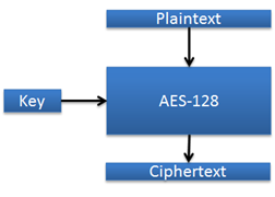
Figure 4.10 AES-ECB (Electronic Code Book)
4.2.6.4.4. AES-128 CCM Encryption and Authentication
\requirement{CC:009F.01.00.11.005}{0}
The payload in the S2 Message Encapsulation Command MUST be encrypted and authenticated using AES-128 CCM. For details about AES-128 CCM and message decryption and validation, refer to [13] and RFC 3610.
CCM takes the following input:
A combined encryption and authentication key denoted
KeyCCMA Nonce
A variable-length additional authenticated data structure (AAD)
A variable-length payload to encrypt and authenticate
CCM yields as output:
An encrypted version of the payload combined with an authentication tag covering the payload and the AAD
4.2.6.4.5. CCM profile
\requirement{CC:009F.01.00.11.006}{0}
RFC 3610 defines a number of parameters that together determine the CCM profile used. S2 nodes MUST use the following parameter values for the CCM profile:
Additional Authenticated Data (AAD) MUST be used (Adata = 1)
The actual AAD is defined in Section 4.2.6.4.5.1.
The Length field MUST be 2 bytes long (L = 2 bytes)
The Authentication tag length MUST be 8 bytes (M = 8 bytes)
The Nonce length MUST be 13 bytes (N = 13 bytes)
\requirement{CC:009F.01.00.11.007}{0}
The following length requirements MUST be observed:
AAD structures of up to 30 bytes MUST be supported. Larger AAD structures MAY be supported.
\requirement{CC:009F.01.00.11.008}{0}
The 13 byte Nonce MUST be generated by taking the 13 most significant bytes of the NextNonce or Nonce0 as described in Section 4.2.6.4.9.
4.2.6.4.5.1. Additional Authenticated Data (AAD)
\requirement{CC:009F.01.00.11.009}{0}
A structure MUST be constructed and used as AAD input for each CCM operation.
If both the Sender NodeID and Destination Tag are less or equal to 255, the following structure MUST be used as ADD:
7 |
6 |
5 |
4 |
3 |
2 |
1 |
0 |
|---|---|---|---|---|---|---|---|
Sender NodeID |
|||||||
Destination Tag |
|||||||
HomeID Byte 1 |
|||||||
… |
|||||||
HomeID Byte 4 |
|||||||
Message Length Byte 1 (MSB) |
|||||||
Message Length Byte 2 (LSB) |
|||||||
Sequence Number |
|||||||
Reserved |
Enc Ext |
Ext |
|||||
Extension Data 1 |
|||||||
… |
|||||||
Extension Data M |
|||||||
If either the Sender NodeID or Destination Tag are greater than 255, the following structure MUST be used as ADD:
7 |
6 |
5 |
4 |
3 |
2 |
1 |
0 |
|---|---|---|---|---|---|---|---|
Sender NodeID (MSB) |
|||||||
Sender NodeID (LSB) |
|||||||
Destination Tag (MSB) |
|||||||
Destination Tag (LSB) |
|||||||
HomeID Byte 1 |
|||||||
… |
|||||||
HomeID Byte 4 |
|||||||
Message Length Byte 1 (MSB) |
|||||||
Message Length Byte 2 (LSB) |
|||||||
Sequence Number |
|||||||
Reserved |
Enc Ext |
Ext |
|||||
Extension Data 1 |
|||||||
… |
|||||||
Extension Data M |
|||||||
Sender NodeID (1 or 2 bytes)
NodeID of the sending node.
Destination Tag (1 or 2 bytes)
The use of this field depends on the actual frame.
\requirement{CC:009F.01.00.11.00A}{0}
If the field is used for a Singlecast frame, this field MUST carry the Receiver NodeID.
If the field is used for an S2 Multicast frame, this field MUST carry the S2 Multicast Group ID.
HomeID (4 bytes)
HomeID of the sending node.
Message length (2 bytes)
This field indicates the total length in bytes of the Security 2 Message Encapsulation Command.
Sequence Number (1 byte)
Refer to the Security 2 Message Encapsulation Command (Section 4.2.6.5.3.3).
Ext (1 bit)
Refer to the Security 2 Message Encapsulation Command (Section 4.2.6.5.3.3).
Enc Ext (1 bit)
Refer to the Security 2 Message Encapsulation Command (Section 4.2.6.5.3.3).
Reserved
Refer to the Security 2 Message Encapsulation Command (Section 4.2.6.5.3.3).
Extension Data (M bytes)
\requirement{CC:009F.01.00.11.00B}{0}
This field MUST contain all non-encrypted extension objects.
\requirement{CC:009F.01.00.11.00C}{0}
This field MUST include the Length and Type fields prepending the actual data of each extension.
4.2.6.4.6. Message Authentication Code - AES-128 CMAC
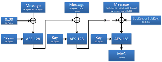
Figure 4.11 AES-128 CMAC building blocks
AES-128 CMAC is used for key derivation and Nonce mixing. The CMAC operation is specified in [15].
4.2.6.4.7. Pseudo Random Number Generator (PRNG)
\requirement{CC:009F.01.00.11.015}{0}
The PRNG MUST be used for:
Generating new network keys when provisioning a new network.
Generating Nonce contributions for synchronizing the SPAN with peer nodes.
\requirement{CC:009F.01.00.11.016}{0}
The PRNG MUST be implemented as an AES-128 CTR_DRBG as specified in [14]. The following profile MUST be used:
No derivation function
No reseeding counter
Personalization string of 0x00 repeated 32 times
Output length = 16 bytes
security_strength is not used
\requirement{CC:009F.01.00.11.017}{0}
The entropy_input [14] for instantiating the PRNG MUST be generated by a truly random source, e.g. white radio noise. The PRNG MUST be hardware seeded.
\requirement{CC:009F.01.00.11.018}{0}
The inner state of the PRNG MUST be separated from the SPAN table.
4.2.6.4.8. Key extraction and derivation
The functions described in this section are used during key exchange.
4.2.6.4.8.1. CKDF-TempExtract
The CKDF-TempExtract function is used to extract the key entropy from the non-uniformly distributed ECDH Shared Secret.
CKDF-TempExtract(ConstantPRK, ECDH Shared Secret, KeyPub_A, KeyPub_B) -> PRK
The function’s input is defined by:
ConstantPRK = 0x33 repeated 16 timesECDH Shared Secret is the output of the ECDH key exchangePublic Keys of Nodes A and BPRK = CMAC(ConstantPRK, ECDH Shared Secret | KeyPub_A | KeyPub_B )
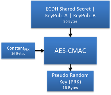
Figure 4.12 CKDF-TempExtract function block diagram
4.2.6.4.8.2. CKDF-TempExpand
\requirement{CC:009F.01.00.11.08D}{0}
Once the PRK has been computed, the temporary Authentication, Encryption and Nonce Keys MUST be derived using the CKDF-TempExpand function [10].
CKDF-TempExpand(PRK, ConstantTE) -> {TempKeyCCM, TempPersonalizationString}
The function’s input is defined by:
PRK is calculated in the previousSection 4.2.6.4.8.1ConstantTE = 0x88 repeated 15 times
Calculations are performed as follows:
T1 = CMAC(PRK, ConstantTE | 0x01)T2 = CMAC(PRK, T1 | ConstantTE | 0x02)T3 = CMAC(PRK, T2 | ConstantTE | 0x03)
Output is defined as follows:
TempKeyCCM = T1. Temporary CCM Key, combined Encryption and Authentication Key.TempPersonalizationString = T2 | T3
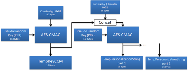
Figure 4.13 CKDF-TempExpand function block diagram
4.2.6.4.8.3. Permanent Key Exchange
\requirement{CC:009F.01.00.13.014}{12} \requirement{CC:009F.01.00.11.08E}{16}
A node that has been security bootstrapped into the network is characterized by being in possession of one or more Network Key(s). This key(s) is used throughout the lifetime of the network, typically measured in years to decades. Different nodes MAY have different Class Keys. A central controller node MUST manage all the keys and select at inclusion time which class key(s) to share with a given node.
\requirement{CC:009F.01.00.11.08F}{0}
Network Keys for all Security 2 Classes MUST be 16 random bytes, generated by using the PRNG function described in Section 4.2.6.7.
4.2.6.4.8.4. Key Derivation
\requirement{CC:009F.01.00.11.090}{4}
Once the Network Key(s) has been exchanged, the KeyCCM, PersonalizationString and KeyMPAN values MUST be derived using the CKDF-NetworkKeyExpand function [10].
CKDF-NetworkKeyExpand (PNK, ConstantNK) -> {KeyCCM, PersonalizationString, KeyMPAN}
The function’s input is defined by:
PNK is the permanent network key.ConstantNK = 0x55 repeated 15 times
Calculations are performed as follow:
T1 = CMAC(PNK, ConstantNK | 0x01)T2 = CMAC(PNK, T1 | ConstantNK | 0x02)T3 = CMAC(PNK, T2 | ConstantNK | 0x03)T4 = CMAC(PNK, T3 | ConstantNK | 0x04)
Output is obtained by:
KeyCCM = T1; CCM Key, combined Encryption and AuthenticationPersonalizationString = T2 | T3KeyMPAN = T4
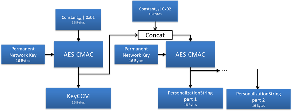
Figure 4.14 CKDF-NetworkKeyExpand function block diagram
4.2.6.4.9. Nonces for CCM
The Nonce is used for the CCM encryption in a Security 2 Message Encapsulation Command. Nonces provide these security benefits:
Replay protection. Replaying an old message will result in the replay being discarded because the Nonce has already been used.
The security proofs for CCM rely on the assumption that the same plaintext is never encrypted under the same key twice. Having unique Nonces upholds this assumption.
Singlecast and Multicast transport use different mechanisms for generating Nonces as described in the following sections.
Singlecast Pre-Agreed Nonces are referred to as SPAN.
Multicast Pre-Agreed Nonces are referred to as MPAN.
4.2.6.4.10. SPAN NextNonce Generator
\requirement{CC:009F.01.00.11.00D}{0}
Singlecast Nonces MUST be generated in the following way:
Skip steps 1 through 3 if a SPAN is already established
Exchange 16 bytes of Entropy between the Sender and the Receiver
Mix the entropy contributions
Instantiate CTR_DRBG and store the working state in the SPAN table
Generate 13 bytes of
Noncefrom the establishedSPANusing the NextNonce function.Save the updated working state in the SPAN table
4.2.6.4.10.1. SPAN Instantiation
\requirement{CC:009F.01.00.11.00E}{0}
The Sender and Receiver MUST instantiate the CTR_DRBG as follows:
The Sender and Receiver MUST exchange 16 bytes of Entropy Input (EI), resulting in 32 bytes of shared entropy
Both contributions MUST be generated using the PRNG (see Section 4.2.6.4.7)
Mix the 32 bytes EI into
MEI, using CKDF-MEI-Extract and CKDF-MEI-Expand functions
\requirement{CC:009F.01.00.11.00F}{0}
The CTR_DRBG MUST be instantiated using the following profile:
Entropy Input =
MEI(obtained with CKDF-MEI_Expand)Personalization_String =
PersonalizationStringOutput length = 16
No derivation function
No reseeding counter
No security_strength
The CTR_DRBG now has its inner state set, referred to as the
InnerSPAN
4.2.6.4.10.1.1. Mixing
Mixing of the two EIs is done by first calling CKDF-MEI-Extract with the EIs as input and using the result as input for CKDF-MEI-Expand
4.2.6.4.10.1.1.1. CKDF-MEI-Extract
CKDF-MEI-Extract(ConstNonce, SenderEI | ReceiverEI) -> NoncePRK
The Input is defined by:
ConstNonce = 0x26 repeated 16 times
The Output is obtained by:
NoncePRK = CMAC(ConstNonce, SenderEI | ReceiverEI)
4.2.6.4.10.1.1.2. CKDF-MEI-Expand
CKDF-MEI-Expand(NoncePRK, ConstEntropyInput) -> MEI
The Input is defined by:
NoncePRK is the pseudo random value obtained in the Extract step/ConstEntropyInput = 0x88 repeated 15 times
The Output is obtained by:
T0 = ConstEntropyInput | 0x00T1 = CMAC(NoncePRK, T0 | ConstEntropyInput | 0x01)T2 = CMAC(NoncePRK, T1 | ConstEntropyInput | 0x02)MEI = T1 | T2
4.2.6.4.10.2. Generation
\requirement{CC:009F.01.00.11.010}{0}
With the CTR_DRBG having its inner state set, new SPANs MUST now be generated by subsequent calls to the NextNonce function.
4.2.6.4.10.2.1. NextNonce
The NextNonce function is defined as the CTR_DRBG_Generate_algorithm [14] with the following parameters:
working_state =
InnerSPANrequested_number_of_bits = 128
additional_input = “” (empty string, i.e. zero bytes)
\requirement{CC:009F.01.00.11.011}{0}
The NextNonce function MUST return a new SPAN for each call. The InnerSPAN MUST be stored in the SPAN table as described in Section 4.2.6.5.1.
\requirement{CC:009F.01.00.11.012}{0}
The 16 bytes of Nonce MUST be truncated to the 13 most significant bytes before passing to the CCM module.
4.2.6.4.11. MPAN NextNonce Generator
\requirement{CC:009F.01.00.11.013}{4}
Multicast Pre-Agreed Nonces (MPAN) are generated by encrypting successive values of a counter. The initial value MUST be a 16 byte random number generated by the PRNG (Section 4.2.6.4.7). Whenever an MPAN is generated and consumed by the CCM module, the inner MPAN state is incremented.
MPAN instantiation and synchronization is described in Section 4.2.6.5.2.
4.2.6.4.11.1. MPAN Generation
\requirement{CC:009F.01.00.11.014}{4}
MPAN generation is needed when a node sends or receives a secure multicast message. The generation procedure, called NextMPAN, MUST comply with the following description:
The node reads the 16-byte inner MPAN state N from the MPAN table.
The node performs an AES-128-ECB encryption of the inner MPAN state N using
KeyMPAN(obtained during Key Derivation) as key.The node generates MPAN N by taking the 13 most significant bytes of the result.
The node increments the inner MPAN state N. The result is the inner MPAN state N+1 which is stored in the MPAN table. The increment operation MUST treat the inner MPAN state as an unsigned 16 byte integer. Thus, incrementing all ones MUST yield all zeros.
The process is also illustrated in Figure 4.15.
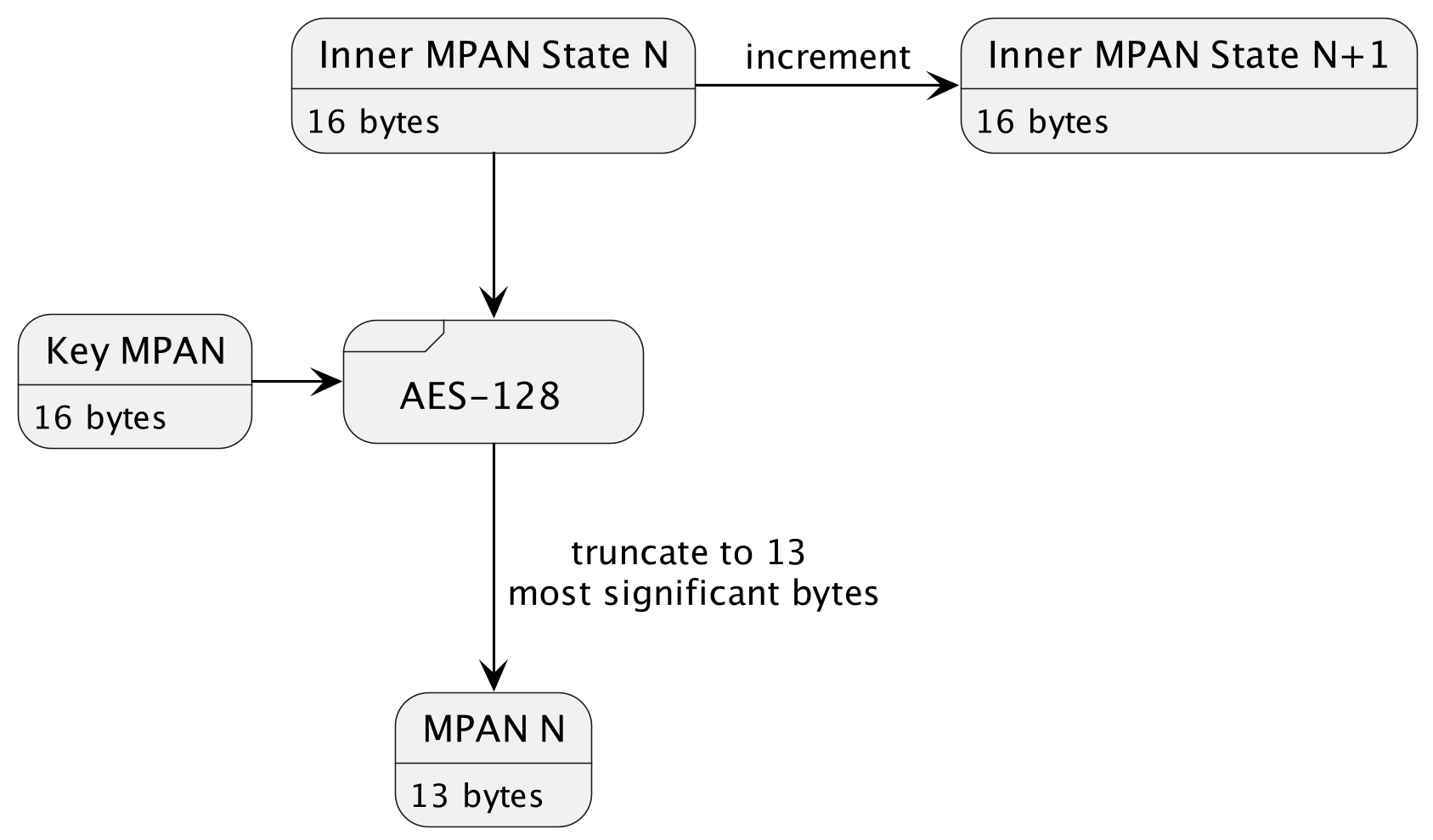
Figure 4.15 MPAN Generation
4.2.6.5. Message Encapsulation
The Security 2 Command Class supports Singlecast as well as Multicast communication
\requirement{CC:009F.01.00.11.019}{0}
The S2 Transport Layer MUST NOT provide retransmission if the security layer discards a message due to SPAN synchronization failure or failed authentication.
\requirement{CC:009F.01.00.12.001}{0}
An application SHOULD use the Supervision Command Class for delivery acknowledgement of Security 2 Encapsulated commands.
\requirement{CC:009F.01.00.12.002}{4}
The Supervision Report command returns high-level status information on the execution status of the transmitted command which SHOULD be used by a controlling application instead of polling the destination node repeatedly.
4.2.6.5.1. Singlecast messages and SPAN Management
Compared to the Security 0 Command Class, the Security 2 Command Class provides a more efficient way to communicate securely. The Security 2 Command Class eliminates the frame overhead of the Security 0 Command Class challenge-response handshake.
\requirement{CC:009F.01.00.11.01A}{0}
Singlecast transport MUST comply with the steps described below:
\requirement{CC:009F.01.00.11.01B}{0}
Before sending an encrypted frame, the Sender MUST establish a Singlecast Pre-Agreed Nonce (SPAN) with the Receiver if a SPAN is not already established.
If a SPAN exists between the two nodes:
Skip to step 3
If the Sender is in possession of a matching Receiver’s Entropy Input:
The Sender uses its PRNG to generate a random 16-byte Nonce (SEI).
The Sender uses the combined 32-byte Sender’s and Receiver’s Entropy Input to instantiate a NextNonce Generator, hence creating the inner SPAN state. (described in Section 4.2.6.4.10)
Skip to step 3
If no SPAN or matching Receiver’s Entropy Input exists between the two parties:
The Sender holds back the frame for subsequent transmission.
The Sender sends a Nonce Get to the Receiver
The Receiver uses its PRNG to generate a random 16-byte Nonce, store it in the SPAN table and send it in a Nonce Report to the Sender, with the Singlecast Out of Sync (SOS) flag set, to indicate that the frame contains a Receiver’s Entropy Input (REI).
The Sender stores the Receiver’s Entropy Input in the SPAN table in the entry matching the receiver’s NodeID.
If the Sender has a pending frame for transmission then proceed to step 3. Otherwise no further action is taken.
The Sender constructs a Security 2 Message Encapsulation Command.
If the inner SPAN state was just created in step 2.a, the SPAN extension containing the SEI is added to the S2 Message encapsulation Command to allow the Receiver to compute the same inner SPAN state.
The Sender creates the next SPAN with the NextNonce function.
The Sender uses the SPAN as IV for the AES-128 CCM encryption and authentication (Section 4.2.6.4.4) of the plaintext payload using
KeyCCM.The Security 2 Message Encapsulation Command is transmitted to the Receiver.
The Receiver inspects the received Security 2 Message Encapsulation Command
\requirement{CC:009F.01.00.12.003}{4} \requirement{CC:009F.01.00.11.01C}{12}
If the Receiver is unable to authenticate the singlecast message with the current SPAN, the Receiver SHOULD try decrypting the message with one or more of the following SPAN values, stopping when decryption is successful or the maximum number of iterations is reached. The maximum number of iterations performed by a receiving node MUST be in the range 1..5.
\requirement{CC:009F.01.00.11.01D}{4} \requirement{CC:009F.01.00.11.01E}{8}
If the maximum number of iterations is reached without successful decryption, a Nonce Report MUST be sent to the Sender with the SOS flag set and containing a new REI. At the same time, the Receiver MUST invalidate the SPAN table entry for the Sender NodeID.
\requirement{CC:009F.01.00.11.01F}{0}
If a SPAN Extension is present, the Receiver MUST:
Instantiate a new SPAN Generator using the Receiver’s Entropy Input stored locally and the Sender’s Entropy Input just received.
Store the inner SPAN state in a SPAN table entry with the Sender as Peer NodeID.
Generate a SPAN by running the NextNonce function on the newly instantiated inner SPAN state.
Attempt authentication with the SPAN.
If the authentication succeeds, skip to step 5.
\requirement{CC:009F.01.00.11.020}{0}
If the authentication fails, the Receiver MUST go to step 2.
\requirement{CC:009F.01.00.11.021}{4}
If the SPAN is already established and a SPAN Extension is not present, the Receiver MUST calculate a new inner SPAN state by passing the old inner SPAN state through the NextNonce function.
After the Receiver has successfully authenticated the encapsulation command, the decrypted payload can be presented to the application layer.
The process is also illustrated in Figure 4.16.
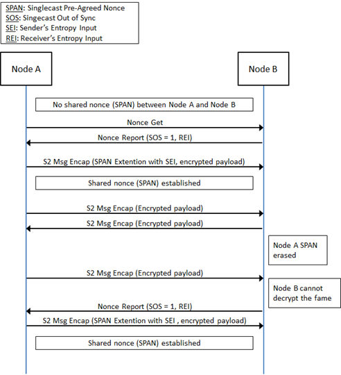
Figure 4.16 Singlecast communication frame flow: Span establishment
4.2.6.5.1.1. SPAN Table
\requirement{CC:009F.01.00.11.022}{0}
A receiving S2 node MUST accept a SPAN table update even if the SPAN table is full.
\requirement{CC:009F.01.00.12.004}{0}
It is RECOMMENDED that the node discards the least recently used entry from the SPAN table to make room for the new entry.
\requirement{CC:009F.01.00.11.0A0}{0}
A supporting node MUST support at least 1 singlecast session (1 SPAN table entry).
Supporting always listening nodes MUST support at least 5 concurrent singlecast sessions (5 SPAN table entries).
\requirement{CC:009F.01.00.12.005}{0}
The following format is RECOMMENDED:
7 |
6 |
5 |
4 |
3 |
2 |
1 |
0 |
|---|---|---|---|---|---|---|---|
Reserved |
Security key |
Nonce Type |
|||||
Sequence Number |
|||||||
SPAN State Byte 1 |
|||||||
… |
|||||||
SPAN State Byte 32 |
|||||||
Peer NodeID |
|||||||
Security key (4 bits)
This field is used to remember which to Security key the SPAN is associated to. An example is given in Table 4.7.
Value |
Description |
|---|---|
0x00 |
ECDH Temporary Key |
0x01 |
S2.2: Access Control |
0x02 |
S2.1: Authenticated |
0x03 |
S2.0: Unauthenticated |
0x04 |
S0 |
Nonce Type (2 bits)
This field is used to advertise the format of the SPAN State field.
\requirement{CC:009F.01.00.12.006}{0}
The field SHOULD be encoded according to Table 4.8.
Nonce Type |
Type |
Description |
|---|---|---|
0x00 |
Free |
Table entry is not used |
0x01 |
Receiver’s Entropy Input (Locally Generated) |
Bytes 1-16 are set to zero Bytes 17-32 contain the Receiver’s Entropy Input |
0x02 |
SPAN state |
Bytes 1-32 contain the SPAN state |
Sequence Number (1 byte)
This field is used to store the sequence number. Refer to description in Security 2 Message Encapsulation Command.
\requirement{CC:009F.01.00.11.024}{0}
A receiving node MUST validate the Sequence Number and the actual sender’s NodeID before accepting a SPAN table update.
SPAN State (32 bytes)
When the Nonce Type is “SPAN state”, this contains the internal state of the NextNonce Generator. When the Nonce Type is Receiver’s Entropy Input this field contains a locally generated Nonce awaiting the matching Sender’s Entropy Input.
Peer NodeID (1 byte)
This field is used to store the NodeID of the corresponding peer.
4.2.6.5.2. Multicast messages and MPAN Management
The S2 Multicast protocol allows a sending node to reach a group of always listening nodes by using pre-agreed information for authentication and encryption.
The following terminology is used in this section:
S2 SC = S2 Singlecast (carried in Z-Wave singlecast frame)
S2 MC = S2 Multicast (carried in Z-Wave broadcast or multicast frame, with the MGRP extension)
S2 SC-F = S2 Singlecast Follow-up (carried in Z-Wave singlecast frame, with the MGRP extension)
\requirement{CC:009F.01.00.11.025}{0}
An S2 Multicast group MUST be represented by a unique (sender NodeID, Group ID) combination.
\requirement{CC:009F.01.00.13.001}{0}
A multicast sender or group owner MAY maintain multiple S2 Multicast groups.
\requirement{CC:009F.01.00.11.026}{0}
Sending and receiving nodes MUST maintain a unique Multicast Pre-Agreed Nonce (MPAN) value for each Group ID.
\requirement{CC:009F.01.00.11.027}{0}
The MPAN is sender specific, and MUST NOT be used by the receiver to send S2 Multicast frames. S2 Multicast can only be performed within a group of nodes in the same S2 Security Class.
All nodes in the network will receive the S2 Multicast frame and will not try to decrypt it if the MPAN of the corresponding (sender NodeID, Group ID) is not known. The S2 Multicast protocol uses S2 SC-F frames for MPAN synchronization.
\requirement{CC:009F.01.00.12.007}{0}
A sending node SHOULD send an S2 SC-F frame to each S2 Multicast group member after sending an S2 MC frame. This ensures that all group members receive the frame and at the same time eliminates the risk of the S2 MC frame being replayed in a delay attack.
\requirement{CC:009F.01.00.12.008}{0}
S2 SC-F SHOULD be sent frequently in order to ensure that MPAN is synchronized at every group member.
S2 Multicast employs a self-healing algorithm for MPAN synchronization. The reception of an S2 SC F allows the receiving node to return an MPAN Out of Sync (MOS) indication (Either using a Nonce Report with the MOS flag or a S2 Message Encapsulation with the MOS extension, refer to Section 4.2.6.5.3.2, Section 4.2.6.5.3.3.1.4) if necessary.
\requirement{CC:009F.01.00.12.009}{0}
Thus, a sending node SHOULD NOT push an up-to-date MPAN before sending an S2 Multicast frame to a new S2 Multicast receiver.
\requirement{CC:009F.01.00.11.028}{0}
A sending node MUST maintain the MPAN inner state according to Table 4.9.
Frame types |
Description |
MPAN increase after transmission |
|---|---|---|
S2 Singlecast |
S2 SC frame |
0 |
S2 Unacknowledged Multicast |
S2 MC frame |
1 |
S2 Acknowledged Multicast |
S2 MC frame followed by an S2 SC-F frame to each S2 Multicast group member |
3 |
\requirement{CC:009F.01.00.11.029}{0}
A receiving node MUST maintain the MPAN inner state according to Table 4.10.
Frame types |
Description |
MPAN increase after transmission |
|---|---|---|
S2 Singlecast |
S2 SC frame |
0 |
S2 Multicast |
S2 MC frame |
1 |
S2 Singlecast Follow-up |
S2 SC-F frame |
1 |
\requirement{CC:009F.01.00.13.002}{0}
If the Receiver is unable to decrypt the S2 MC frame with the current MPAN, the Receiver MAY try decrypting the frame with one or more of the subsequent MPAN values, stopping when decryption is successful or the maximum number of iterations is reached.
\requirement{CC:009F.01.00.12.00A}{0}
The maximum number of iterations performed by a receiving node MUST be 5.
\requirement{CC:009F.01.00.11.02A}{0}
If the maximum number of iterations is reached without successful decryption, the MOS flag MUST be set for the actual Group ID. The MOS state is reported back to the sending node only if the node receives a SC-F for the actual group.
\requirement{CC:009F.01.00.11.0A1}{0}
An always listening node MUST support being member of at least 5 multicast groups at the same time (5 MPAN table entries)
MPAN synchronization and state maintenance examples are given in Figure 4.17 and Figure 4.18.
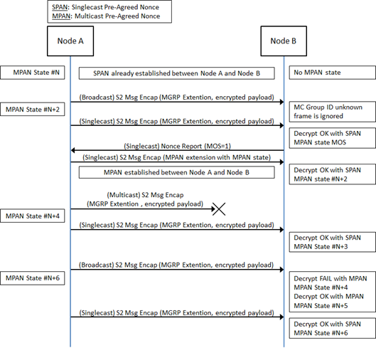
Figure 4.17 Next MPAN calculation example
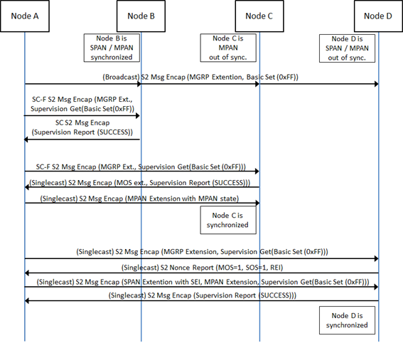
Figure 4.18 Multicast communication example with receivers out of sync and Supervision
\requirement{CC:009F.01.00.11.0A2}{4}
Figure 4.18 shows Node C returning a Supervision Report with the MOS extension after the Supervision encapsulated Singlecast follow-up. In this case, a node MUST NOT return a Nonce Report with the MOS flag and subsequently another frame carrying the Supervision Report.
\requirement{CC:009F.01.00.11.0A3}{0}
The following behavior is REQUIRED when a node is in MOS state and receives a Singlecast Follow-up:
\requirement{CC:009F.01.00.11.0A4}{0}
If the Singlecast Follow-up uses Supervision encapsulation, the receiving node MUST return a Supervision Report with the MOS extension.
\requirement{CC:009F.01.00.11.0A5}{0}
If the Singlecast Follow-up does not use Supervision encapsulation, the receiving node MUST return a Nonce Report with the MOS field set to 1.
4.2.6.5.2.1. MPAN table
\requirement{CC:009F.01.00.12.00B}{0}
A node SHOULD maintain the information indicated in Table 4.11 for each multicast group. The actual implementation format is out of scope of this specification.
Information |
Description |
|---|---|
Owner NodeID |
The NodeID of the node distributing this MPAN (rx only) |
Group ID |
Unique ID chosen by the owner node |
MPAN Inner State |
MPAN inner state used for encryption and decryption |
MPAN entry state |
MPAN_FREE
MPAN_USED
MPAN_MOS
|
\requirement{CC:009F.01.00.11.0AC}{0}
A supporting node MUST support at least 1 multicast session as a receiver (1 MPAN table entry).
4.2.6.5.2.2. Adding an S2 Multicast group member
A group member can be added to a S2 Multicast group by sending a Singlecast follow-up message to the new NodeID after a S2 Multicast message. The newly added NodeID will notify the sender that it is not synchronized for the given Group ID and it will be synchronized when receiving the next singlecast frame.
\requirement{CC:009F.01.00.12.017}{0}
S2 Multicast will not work with sleeping nodes A sending node SHOULD NOT try to add sleeping nodes to a Multicast group.
4.2.6.5.2.3. Removing an S2 Multicast group member
\requirement{CC:009F.01.00.11.099}{12}
A node can be removed from an S2 Multicast group by shuffling the MPAN state. At the next S2 Multicast frame, the newly removed node will set in MOS state and wait for re-synchronization in the next singlecast messages. When the newly removed node receives subsequent singlecast messages without MPAN extension, the newly removed node MUST forget about the Multicast group ID.
4.2.6.5.2.4. Handling a missing S2 Multicast frame
An S2 MC frame may be missing due to simple radio interference or a deliberate delay attack.
In either case, the MPAN needs to be re-synchronized. Further, the MPAN needs to be advanced immediately to close the time window where an attacker can replay the stolen S2 MC frame.
The transmission of a singlecast follow-up frame ensures re-synchronization and prevents a potential delay attack. Figure 4.17 outlines an example of the MPAN state changes when an S2 MC frame is missing.
In the case both multicast and singlecast follow-up frames are intercepted for a delay attack, the attacker has the possibility to replay the multicast frame at a later time. Using the Supervision Command Class in singlecast follow-up frames prevent this attack as the receiving node needs to report the application level status in a new singlecast frame.
4.2.6.5.3. Message encapsulation commands
This section presents the commands of the Security 2 Command Class used for message encapsulation.
4.2.6.5.3.1. Security 2 Nonce Get Command
This command is used to request a fresh Nonce.
\requirement{CC:009F.01.01.11.001}{0}
The Security 2 Nonce Report Command MUST be returned in response to this command.
\requirement{CC:009F.01.01.12.007}{0}
Nodes controlling WOEEN devices are RECOMMENDED to handle the S2 Nonce Get and send S2 Nonce Report within less than 50 ms to reduce wait times for battery-powered and battery-less devices.
\requirement{CC:009F.01.01.11.002}{0}
A node sending this command MUST accept a delay up to <Previous Round-trip-time to peer node> + 250 ms before receiving the Security 2 Nonce Report Command, except for a WOEEN for which the delay before receiving the Security 2 Nonce Report Command is 50 ms, in self-powered mode.
\requirement{CC:009F.01.01.11.003}{0}
This command MUST NOT be issued via multicast addressing.
A receiving node MUST NOT return a response if this command is received via multicast addressing. The Z-Wave Multicast frame, the broadcast NodeID and the Multi Channel multi-End Point destination are all considered multicast addressing methods.
7 |
6 |
5 |
4 |
3 |
2 |
1 |
0 |
|---|---|---|---|---|---|---|---|
Command Class = COMMAND_CLASS_SECURITY_2 (0x9F) |
|||||||
Security Header = SECURITY_2_NONCE_GET (0x01) |
|||||||
Sequence Number |
|||||||
Sequence Number (1 byte)
\requirement{CC:009F.01.01.11.004}{0}
A sending node MUST specify a unique sequence number starting from a random value. Each message MUST carry an increment of the value carried in the previous outgoing message.
\requirement{CC:009F.01.01.11.005}{0}
A receiving node MUST validate the Sequence Number and the actual sender’s NodeID before accepting this command.
\requirement{CC:009F.01.01.11.006}{0}
A receiving node MUST use this field for duplicate detection. Refer to Section 4.2.6.5.4.
4.2.6.5.3.2. Security 2 Nonce Report Command
\requirement{CC:009F.01.02.11.001}{4}
This command is used to advertise a fresh Nonce in preparation for secure communication. This command MUST NOT be issued unless it is done in response to the S2 Nonce Get or the S2 Message Encapsulation Command.
\requirement{CC:009F.01.02.11.002}{0}
A sending node MUST set at least one of the MOS and SOS flags to the value ‘1’ in this command. The command MUST NOT be sent if both the MOS and SOS flags are cleared.
\requirement{CC:009F.01.02.11.003}{0}
A receiving node MUST update the MPAN and/or SPAN of the node sending this command by adding a SPAN and/or MPAN extension to the next Security 2 Message Encapsulation Command.
7 |
6 |
5 |
4 |
3 |
2 |
1 |
0 |
|---|---|---|---|---|---|---|---|
Command Class = COMMAND_CLASS_SECURITY_2 (0x9F) |
|||||||
Command = SECURITY_2_NONCE_REPORT (0x02) |
|||||||
Sequence Number |
|||||||
Reserved |
MOS |
SOS |
|||||
Receiver’s Entropy Input Byte 1 (Optional) |
|||||||
… |
|||||||
Receiver’s Entropy Input Byte N (Optional) |
|||||||
Sequence Number (1 byte)
\requirement{CC:009F.01.02.11.004}{0}
A sending node MUST specify a unique sequence number starting from a random value. Each message MUST carry an increment of the value carried in the previous outgoing message.
\requirement{CC:009F.01.02.11.005}{0}
A receiving node MUST use this field for duplicate detection. Refer to Section 4.2.6.5.4.
Reserved
\requirement{CC:009F.01.02.11.006}{0}
This field MUST be set to 0 by a sending node and MUST be ignored by a receiving node.
SOS - SPAN out of Sync (1 Bit)
\requirement{CC:009F.01.02.11.007}{0}
When set by a sending node, the value ‘1’ MUST indicate that the sending node does not have a SPAN established for the receiving node or was unable to decrypt the most recently received singlecast Security 2 Message Encapsulation Command from the destination of this command.
\requirement{CC:009F.01.02.11.008}{0}
The value ‘0’ MUST indicate that there was no problem decrypting the most recently received singlecast Security 2 Message Encapsulation Command.
\requirement{CC:009F.01.02.11.009}{0}
If the SOS flag is set to ‘1’, the REI field MUST be included in the command.
If the SOS flag is set to ‘0’, the REI field MUST NOT be included in the command.
\requirement{CC:009F.01.02.11.00A}{0}
A receiving node MUST establish a new Singlecast Pre-Agreed Nonce (SPAN) and return a Security 2 Message Encapsulation Command with the SPAN extension, if this flag is set to ‘1’ by a sending node.
MOS - MPAN Out of Sync (1 Bit)
\requirement{CC:009F.01.02.11.00B}{0}
When set by a sending node, the value ‘1’ MUST indicate that the sending node does not have a MPAN state for Multicast group used in the most recently received singlecast follow-up Security 2 Message Encapsulation Command from the destination of this command.
\requirement{CC:009F.01.02.11.00C}{0}
The value ‘0’ MUST indicate that there was no problem decrypting the most recently received multicast Security 2 Message Encapsulation Command that was followed by a singlecast follow-up.
\requirement{CC:009F.01.02.11.00D}{0}
A sending node MUST NOT advertise the MOS flag for a given (source NodeID, Group ID) tuple more than one time.
\requirement{CC:009F.01.02.11.00E}{0}
If this flag is set to ‘1’ by a sending node, a receiving node MUST transfer the Multicast Pre-Agreed Nonce (MPAN) of the most recent singlecast follow-up transmission in a subsequent singlecast message if the sending node belongs to the multicast group. The MPAN MUST be transferred by sending a singlecast Security 2 Message Encapsulation Command with the MPAN extension.
Receiver’s Entropy Input (REI) (16 Bytes)
This field is optional. When present, this field is used to carry the Receiver’s Entropy Input in preparation for new S2 transmissions based on the SPAN. Refer to Section 4.2.6.5.1.
\requirement{CC:009F.01.02.11.00F}{0}
If the SOS flag is set to ‘1’, the REI field MUST be included in the command.
If the SOS flag is set to ‘0’, the REI field MUST NOT be included in the command.
4.2.6.5.3.3. Security 2 Message Encapsulation Command
\requirement{CC:009F.01.03.11.001}{0}
The Security 2 Nonce Report Command MUST be returned in response to this command if the receiving node fails decrypting the command or if the message contains an MGRP extension with a Group ID that is unknown or out of sync (MOS).
\requirement{CC:009F.01.03.13.001}{0}
This command MAY be issued via Z-Wave Multicast addressing.
\requirement{CC:009F.01.03.11.002}{0}
A receiving node MUST NOT return a response if this command is received via Z-Wave Multicast addressing. The Z-Wave Multicast frame and the broadcast NodeID are both considered Z-Wave Multicast addressing methods.
7 |
6 |
5 |
4 |
3 |
2 |
1 |
0 |
|---|---|---|---|---|---|---|---|
Command Class = COMMAND_CLASS_SECURITY_2 (0x9F) |
|||||||
Security Header = SECURITY_2_MESSAGE_ENCAPSULATION (0x03) |
|||||||
Sequence Number |
|||||||
Reserved |
Encrypted Extension |
Extension |
|||||
Extension 1 Length |
|||||||
More to follow |
Critical |
Extension 1 Type |
|||||
Extension 1 Byte 1 |
|||||||
… |
|||||||
Extension 1 Byte K |
|||||||
Extension 2 Length |
|||||||
More to follow |
Critical |
Extension 2 Type |
|||||
Extension 2 Byte 1 |
|||||||
… |
|||||||
Extension 2 Byte L |
|||||||
Encrypted Extension 1 Length |
|||||||
More to follow |
Critical |
Encrypted Extension 1 Type |
|||||
Encrypted Extension 1 Byte 1 |
|||||||
… |
|||||||
Encrypted Extension 1 Byte M |
|||||||
Encrypted Extension 2 Length |
|||||||
More to follow |
Critical |
Encrypted Extension 2 Type |
|||||
Encrypted Extension 2 Byte 1 |
|||||||
… |
|||||||
Encrypted Extension 2 Byte N |
|||||||
CCM Ciphertext object Byte 1 |
|||||||
… |
|||||||
CCM Ciphertext object Byte P |
|||||||
Sequence Number (1 byte)
\requirement{CC:009F.01.03.11.003}{0}
A sending node MUST specify a unique sequence number starting from a random value. Each new message MUST carry an increment of the value carried in the previous singlecast command.
\requirement{CC:009F.01.03.11.004}{0}
A receiving node MUST use this field for singlecast duplicate detection. Refer to Section 4.2.6.5.4.
Reserved
\requirement{CC:009F.01.03.11.005}{0}
This field MUST be set to 0 by a sending node and MUST be ignored by a receiving node.
However, the value MUST be used as part of the AAD input (Section 4.2.6.4.5.1) used for authentication of the frame by the sending node as well as the receiving node.
Extension (1 bit)
This field is used to indicate if one or more non-encrypted extensions are included.
\requirement{CC:009F.01.03.11.006}{0}
The value ‘1’ MUST indicate that non-encrypted extensions are included.
The value ‘0’ MUST indicate that non-encrypted extensions are not included.
Refer to the Extension object field description.
Encrypted Extension (1 bit)
This field is used to indicate if one or more encrypted extensions are included.
\requirement{CC:009F.01.03.11.007}{0}
The value ‘1’ MUST indicate that encrypted extensions are included.
The value ‘0’ MUST indicate that encrypted extensions are not included.
Refer to the Encrypted Extension object field description.
[Extension Object] (N instances)
7 |
6 |
5 |
4 |
3 |
2 |
1 |
0 |
|---|---|---|---|---|---|---|---|
Extension Length |
|||||||
More to follow |
Critical |
Type |
|||||
Extension Byte 1 |
|||||||
… |
|||||||
Extension Byte L |
|||||||
Extension Length (1 byte)
This field specifies the length of this extension, in bytes, including the “Extension Length” field.
Type (6 bit)
This field defines the type of this extension. Valid extension types are listed in Section 4.2.6.5.3.3.1.
Critical (1 bit)
\requirement{CC:009F.01.03.11.008}{0}
A receiving node MUST discard the entire command if this flag is set to ‘1’ and the Type field advertises a value that the receiving node does not support.
\requirement{CC:009F.01.03.11.009}{0}
If this flag is set to ‘0’ and the Type field advertises a value that the receiving node does not support, the actual extension MUST be ignored.
\requirement{CC:009F.01.03.12.001}{0}
A receiving node SHOULD continue processing of the encapsulation command after the discarded extension.
More to Follow (1 bit)
\requirement{CC:009F.01.03.11.00A}{0}
If the More to Follow flag is set to ‘1’, another Extension Object MUST follow this Extension Object.
Extension (Variable length)
\requirement{CC:009F.01.03.11.00B}{4}
This field carries the actual extension. Refer to Section 4.2.6.5.3.3.1. The length of this field MUST comply with the length specified in the Extension Length field of this Extension Object.
[Encrypted Extension Object] (N instances)
\requirement{CC:009F.01.03.11.00C}{0}
The format of this object is identical to the unencrypted Extension Object. However, this object MUST be part of the encrypted payload.
CCM Ciphertext Object (P bytes)
This field contains an encrypted message. It comprises:
(Optional) Complete Z-Wave command (comprising Command Class Identifier, Command Identifier and optional command payload)
CCM control data
CCM authentication tag.
The preceding Encrypted Extension fields are technically also a part of the CCM ciphertext object. But conceptually they are separate from the message and have been described as such.
4.2.6.5.3.3.1. Valid Extensions and Encrypted Extensions
The defined extension types are listed in Table 4.12.
Extension Type Identifier |
Format |
Content Protection |
|---|---|---|
0x01 |
SPAN Extension |
Not Encrypted |
0x02 |
MPAN Extension |
Encrypted |
0x03 |
MGRP Extension |
Not Encrypted |
0x04 |
MOS Extension |
Not Encrypted |
\requirement{CC:009F.01.03.11.00D}{0}
All other values are reserved and MUST NOT be used by a sending node. Reserved values MUST be ignored by a receiving node.
4.2.6.5.3.3.1.1. SPAN Extension
The SPAN Extension is used by the sender to establish a SPAN by sending a Sender’s Entropy Input to the Receiver. The combined Sender’s and Receiver’s Entropy Input may then be passed through the NextNonce function to generate the SPAN.
\requirement{CC:009F.01.03.11.00E}{0}
This extension MUST be sent unencrypted.
7 |
6 |
5 |
4 |
3 |
2 |
1 |
0 |
|---|---|---|---|---|---|---|---|
Length = 18 |
|||||||
More to follow |
Critical = 1 |
Type = SPAN Extension = 1 |
|||||
Sender’s Entropy Input Byte 1 |
|||||||
… |
|||||||
Sender’s Entropy Input Byte 16 |
|||||||
Length (1 byte)
\requirement{CC:009F.01.03.11.00F}{0}
This field MUST be set to 18.
Type (6 bits)
\requirement{CC:009F.01.03.11.010}{0}
This field MUST be set to the SPAN Extension type (1).
Critical (1 bit)
\requirement{CC:009F.01.03.11.011}{0}
This flag MUST be set to ‘1’.
More to Follow (1 bit)
\requirement{CC:009F.01.03.11.012}{0}
If this flag is set to ‘1’, another unencrypted Extension Object MUST follow this unencrypted Extension Object.
If this flag is set to ‘0’, this MUST be the last unencrypted Extension Object.
Sender’s Entropy Input (16 bytes)
\requirement{CC:009F.01.03.11.013}{0}
This field MUST carry the entropy input contribution used to instantiate a NextNonce Generator.
4.2.6.5.3.3.1.2. MPAN Extension
The MPAN Extension is used by the sender to establish or update an MPAN by sending the full 16 bytes MPAN state to the receiver to enable the reception of encrypted multicast transmissions.
\requirement{CC:009F.01.03.11.014}{0}
This extension MUST be sent encrypted.
7 |
6 |
5 |
4 |
3 |
2 |
1 |
0 |
|---|---|---|---|---|---|---|---|
Length = 19 |
|||||||
More to follow |
Critical = 1 |
Type = MPAN Extension = 2 |
|||||
Group ID |
|||||||
Inner MPAN state Byte 1 |
|||||||
… |
|||||||
Inner MPAN state Byte 16 |
|||||||
Length (1 byte)
\requirement{CC:009F.01.03.11.015}{0}
This field MUST be set to 19.
Type (6 bits)
\requirement{CC:009F.01.03.11.016}{0}
This field MUST be set to the MPAN Extension type (2).
Critical (1 bit)
\requirement{CC:009F.01.03.11.017}{0}
This flag MUST be set to ‘1’.
More to Follow (1 bit)
\requirement{CC:009F.01.03.11.018}{0}
If this flag is set to ‘1’, another encrypted Extension Object MUST follow this encrypted Extension Object.
If this flag is set to ‘0’, this MUST be the last encrypted Extension Object.
Group ID (1 byte)
\requirement{CC:009F.01.03.11.019}{0}
This field is used to identify MPAN instances. A sending node MUST set this value to the Group ID of the most recently transmitted multicast frame. The value MUST be in the range 0..255.
\requirement{CC:009F.01.03.11.02D}{0}
A sending node creating a new group SHOULD NOT use the value 0.
\requirement{CC:009F.01.03.11.01A}{0}
A receiving node MUST use this value in combination with the Owner NodeID for identifying the correct MPAN table entry when an MPAN table entry to use for frame decryption or MPAN updates.
\requirement{CC:009F.01.03.11.01B}{0}
If a receiving node already has an MPAN for the actual Group ID, that MPAN MUST be updated.
\requirement{CC:009F.01.03.12.002}{4}
If this is a new Group ID, the new information MUST be stored. This may require the deletion of another MPAN table entry. It is RECOMMENDED that the least recently used entry is deleted.
Inner MPAN state (16 bytes)
This field carries the value to be used in the encryption and decryption of the next S2 Multicast frame.
4.2.6.5.3.3.1.3. MGRP Extension
\requirement{CC:009F.01.03.11.01C}{0}
The Multicast Group (MGRP) Extension MUST be included in all S2 Multicast and S2 Singlecast follow-up frames.
\requirement{CC:009F.01.03.11.01D}{0}
A receiving node MUST use the Group ID to select the MPAN for decrypting this message.
\requirement{CC:009F.01.03.11.01E}{0}
When receiving this extension, the matching MPAN (if found) MUST be incremented by one after decryption.
\requirement{CC:009F.01.03.11.02B}{4}
If the Group ID is not found in the receiver MPAN table and the received frame is a singlecast (follow-up), the node MUST return a Nonce Report with the MOS flag set, or alternatively, return another Security 2 Message Encapsulation Command with the MOS extension included.
\requirement{CC:009F.01.03.11.020}{0}
This extension MUST NOT be sent together with the MPAN extension.
\requirement{CC:009F.01.03.11.021}{0}
This extension MUST be sent unencrypted.
7 |
6 |
5 |
4 |
3 |
2 |
1 |
0 |
|---|---|---|---|---|---|---|---|
Length = 3 |
|||||||
More to follow |
Critical = 1 |
Type = MGRP Extension = 3 |
|||||
Group ID |
|||||||
Length (1 byte)
\requirement{CC:009F.01.03.11.022}{0}
This field MUST be set to 3.
Type (6 bits)
\requirement{CC:009F.01.03.11.023}{0}
This field MUST be set to the MGRP Extension type (3).
Critical (1 bit)
\requirement{CC:009F.01.03.11.024}{0}
This flag MUST be set to ‘1’.
More to Follow (1 bit)
\requirement{CC:009F.01.03.11.025}{0}
If this flag is set to ‘1’, another unencrypted Extension Object MUST follow this unencrypted Extension Object.
If this flag is set to ‘0’, this MUST be the last unencrypted Extension Object.
Group ID (1 byte)
This field is used by the sender to uniquely identify which MPAN was used to encrypt this multicast frame.
4.2.6.5.3.3.1.4. MOS Extension
The MOS extension is used to indicate that the sending node does not have a MPAN state for the Multicast group used in the most recently received singlecast follow-up Security 2 Message Encapsulation Command from the destination of this command
\requirement{CC:009F.01.03.13.002}{0}
The receiver MAY choose to re-synchronize the sending node by returning a new Security 2 Message Encapsulation Command with a MPAN extension included.
\requirement{CC:009F.01.03.11.026}{0}
This extension MUST be sent unencrypted.
7 |
6 |
5 |
4 |
3 |
2 |
1 |
0 |
|---|---|---|---|---|---|---|---|
Length = 2 |
|||||||
More to follow |
Critical = 1 |
Type = MOS Extension = 4 |
|||||
Length (1 byte)
\requirement{CC:009F.01.03.11.027}{0}
This field MUST be set to 2.
Type (6 bits)
\requirement{CC:009F.01.03.11.028}{0}
This field MUST be set to the MOS Extension type (4).
Critical (1 bit)
\requirement{CC:009F.01.03.11.02C}{0}
This flag MUST be set to ‘0’.
More to Follow (1 bit)
\requirement{CC:009F.01.03.11.02A}{0}
If this flag is set to ‘1’, another unencrypted Extension Object MUST follow this unencrypted Extension Object.
If this flag is set to ‘0’, this MUST be the last unencrypted Extension Object.
4.2.6.5.4. Duplicate Message Detection
\requirement{CC:009F.01.00.11.0AD}{0}
A sending node MUST set the Sequence Number to a random value on startup. The Sequence Number MUST be incremented for the transmission of each new unique singlecast (and singlecast follow-up) transmission.
\requirement{CC:009F.01.00.11.02D}{0}
A receiving node MUST use the Sequence Number field in the Nonce Get, Nonce Report and Message Encapsulation commands for duplicate detection.
\requirement{CC:009F.01.00.11.02E}{0}
Duplicates of recently received commands MUST be discarded.
\requirement{CC:009F.01.00.12.00C}{0}
The following algorithm SHOULD be used for duplicate detection of singlecast messages:
\requirement{CC:009F.01.00.11.02F}{0}
If an incoming sequence number and Peer NodeID match an entry in the SPAN table, the frame MUST be discarded.
\requirement{CC:009F.01.00.11.030}{0}
If it is a new sequence number, the received sequence number and Peer NodeID MUST be stored in the SPAN table.
4.2.6.6. Key Management
\requirement{CC:009F.01.00.11.033}{0}
S2 communication relies on two separate derived keys that MUST be shared between any nodes communicating with each other; the combined Encryption and Authentication Key denoted KeyCCM and the CTR_DRBG Key denoted PersonalizationString. Both keys MUST be derived from one Network Key that is exchanged between the nodes using the CKDF-NetworkKeyExpand function detailed in Section 4.2.6.4.8.4.
\requirement{CC:009F.01.00.11.034}{8}
In S2, not all nodes share the same network key. S2 separates devices into different Security Classes, so that if one Security Class is compromised, it does not affect other Security Classes. The joining node MUST advertise the supported Security Classes during the S2 bootstrapping process.
\requirement{CC:009F.01.00.13.003}{0}
The including node MAY grant membership of one or more Security Classes.
\requirement{CC:009F.01.00.11.035}{0}
The joining node MUST then request the granted keys, one at a time.
The Security Classes are listed in Table 4.13.
S2 Access Control and S2 Authenticated Security Classes are equivalent from a technical perspective, but do not share the same network key. This is simply to prevent compromising the Access Control key if the Authenticated key is compromised.
Client-side authentication is an alternative authentication mechanism intended for the authenticated security bootstrapping of devices which do not have a DSK. Refer to Section 4.2.6.6.3.
Value |
Class Name |
Example Devices |
Controller authentication (Refer to Section 4.2.6.6.2) |
Client-side authentication (Refer to Section 4.2.6.6.3) |
||
|---|---|---|---|---|---|---|
Display DSK |
Input DSK |
Display DSK |
Input DSK |
|||
2 |
S2 Access Control |
Door locks, Garage doors |
14 bytes |
5 decimal digits (2 bytes) |
12 bytes (Optional) |
10 decimal digits (4 bytes) |
None (QR Code) |
QR Code (16 bytes) |
None (QR Code) |
QR Code (16 bytes) |
|||
1 |
S2 Authenticated |
Lighting and Sensors (Managed systems and security systems) |
14 bytes |
5 decimal digits (2 bytes) |
12 bytes (Optional) |
10 decimal digits (4 bytes) |
None (QR Code) |
16 bytes (QR Code) |
None (QR Code) |
16 bytes (QR Code) |
|||
0 |
S2 Unauthenticated |
Lighting and Sensors (Unmanaged systems) |
0 to 16 bytes |
0 |
0 |
0 |
7 |
S0 |
Legacy door locks |
N/A |
N/A |
N/A |
N/A |
\requirement{CC:009F.01.00.11.036}{0}
All other values are reserved and MUST NOT be used by a sending node. Reserved values MUST be ignored by a receiving node.
The manufacturer decides which classes are relevant to advertise for the intended use of the product. For instance:
A light dimmer device may advertise the S2 Unauthenticated Class and the S2 Authenticated Class as the intended classes. If a constrained key fob without display is used to create a small system, the wall controller may grant only the S2 Unauthenticated Class to the light dimmer, which then requests only the S2 Unauthenticated Class key.
A light bulb may advertise the S2 Unauthenticated Class as its only intended class because it does not provide a DSK. Depending on the configured security level, an authentication capable gateway may accept including S2 Unauthenticated Class devices or it may reject including S2 Unauthenticated Class-only devices.
A door lock device may advertise the S2 Access Control Class as its only intended class because it requires the highest protection level. A constrained key fob, which can grant only the S2 Unauthenticated Class key, rejects including the door lock device and returns an error indication to the user because it cannot authenticate the door lock.
4.2.6.6.1. Key Exchange
The S2 key exchange MUST comply with Table 4.14.
Key to be exchanged |
Key to use for the Key Exchange |
Key to use for the Key Verification |
|---|---|---|
S2.2: Access Control |
ECDH Temporary Key |
S2.2 |
S2.1: Authenticated |
ECDH Temporary Key |
S2.1 |
S2.0: Unauthenticated |
ECDH Temporary Key |
S2.0 |
S0 |
ECDH Temporary Key |
S0 |
\requirement{CC:009F.01.00.11.039}{0}
A number of Security Class keys may be granted to the joining node. A temporary key and SPAN MUST be used for the exchange of the Security Class keys.
\requirement{CC:009F.01.00.11.03A}{0}
The temporary SPAN MUST be initialized with the Shared Nonce that is established after the S2 temporary key is established.
\requirement{CC:009F.01.00.11.03B}{0}
The SPAN value MUST be updated after each Security Class key exchange.
\requirement{CC:009F.01.00.11.03C}{0}
Verification of an assigned key (including S0) MUST always use the newly exchanged key to encrypt the S2 verification message.
\requirement{CC:009F.01.00.11.040}{0}
If a joining node is unsuccessful requesting all the Security Class keys that it was granted, the node MUST abort the S2 bootstrapping entirely.
\requirement{CC:009F.01.00.11.0B6}{4}
The S0 key can be exchanged with the Security 0 Command Class or with the Security 2 Command Class. An S2 node MUST NOT allow S0 bootstrapping after a failed S2 bootstrapping initiated by the controller.
\requirement{CC:009F.01.00.11.0B4}{4}
The S0 message encapsulation MUST be done with the Security 0 Command Class encapsulation Command after S2 bootstrapped is completed.
4.2.6.6.2. ECDH key pairs, Device Specific Key and User Verification
A Device Specific Key (DSK) is used to protect against man-in-the-middle attacks (MITM) where a malicious attacker tries to intercept and manipulate the key exchange.
\requirement{CC:009F.01.00.11.0BA}{0}
A node supporting S2 MUST have a first Learn Mode ECDH key pair:
This key pair is used for joining a network both with and without authentication during S2 Bootstrapping. However, if the node also has a second Learn Mode ECDH key pair, then the first key pair is only used when the S2 Bootstrapping requires authentication.
This key pair MUST be static.
\requirement{CC:009F.01.00.13.019}{0}
A node supporting S2 MAY have a second Learn Mode ECDH key pair:
This key pair is used for joining a network when the S2 Bootstrapping does not require authentication.
This key pair MAY be dynamic.
\requirement{CC:009F.01.00.11.0BB}{0}
Additionally, a node able to perform S2 bootstrapping MUST have an additional separate Add Mode ECDH key pair:
This key pair is used for adding nodes into a network (controller side).
This key pair MUST be dynamic.
\requirement{CC:009F.01.00.11.0B7}{0}
A unique Authenticated Learn Mode ECDH key pair MUST be assigned to each individual node, if they request an Authenticated Security Class.
\requirement{CC:009F.01.00.13.018}{0}
A node MAY create a new Unauthenticated Learn Mode ECDH key pair for every S2 bootstrapping attempt.
\requirement{CC:009F.01.00.11.0B8}{0}
A node MUST keep the same Authenticated Learn Mode ECDH key pair for the lifetime of the node.
\requirement{CC:009F.01.00.11.0B9}{0}
The DSK is defined as the first 16 bytes of the Authenticated ECDH Public Key of a node. An S2 node MUST respect the DSK requirements listed in [35].
The DSK may be used for out-of-band (OOB) authentication in two ways.
The including controller uses QR code scanning to read the entire DSK off the joining device and match it with the obfuscated public key received via RF from the joining device.
Else the including controller asks the user to visually validate that the rest of the DSK matches with the Public Key received via RF. The including controller additionally asks the user to enter the PIN code (the 5 first digits of the DSK string) in order to substitute the obfuscated bytes of the joining node’s Public Key.
\requirement{CC:009F.01.00.12.011}{0}
An including controller with support for the S2 Authenticated Class or the S2 Access Control Class SHOULD provide a QR code scanning capability for user friendly inclusion.
\requirement{CC:009F.01.00.11.04E}{0}
If scanning capability is not available, the including controller MUST provide an interface that allows the user to enter a 5 digit PIN code and perform visual DSK string validation.
\requirement{CC:009F.01.00.11.04F}{0}
The requested PIN code MUST be the first 5 decimal digits of the DSK string.
4.2.6.6.3. Client-Side Authentication
\requirement{CC:009F.01.00.11.06E}{0}
When upgrading existing devices to support Security 2 through an over-the-air (OTA) firmware update, there is no DSK printed on the node and the upgraded node MUST therefore generate its public key and DSK internally with the updated firmware.
\requirement{CC:009F.01.00.13.00C}{0} \requirement{CC:009F.01.00.11.06F}{4}
A device MAY request the use of Client-Side authentication (CSA) if it does not possess a DSK label. If the joining node requests CSA, the including controller MUST ask the user if this should be permitted, and if permitted, the including controller MUST display its own DSK.
\requirement{CC:009F.01.00.11.070}{0}
As stated in Table 4.13, the first 10 digits MUST be input on the Joining Node, meaning it MUST have a method of input, like a keypad.
\requirement{CC:009F.01.00.11.071}{0}
Compared to controller-side authentication where the entire DSK MUST also be visually verified, CSA does come with a higher risk of having the bootstrapping attempt manipulated by an attacker. The attacker, however, has to guess 4 random bytes in one attempt.
4.2.6.6.4. Initial Key Exchange
\requirement{CC:009F.01.00.11.0A6}{0}
Add mode MUST be initiated physically. Physical activation includes button press, applying power, remote user activation, etc.
\requirement{CC:009F.01.00.11.052}{0}
Initial Key Exchange MUST be carried out using the ECDH temporary key with the including controller.
\requirement{CC:009F.01.00.11.053}{0}
The Including Node A MUST create a new Add Mode ECDH Key Pair for each new bootstrapping process (regardless of the outcome of each bootstrapping attempt), if it supports the S2 Access Control and/or S2 Authentication Security Classes.
\requirement{CC:009F.01.00.11.055}{0}
The Key Exchange process MUST follow the frame flow illustrated in Figure 4.19.
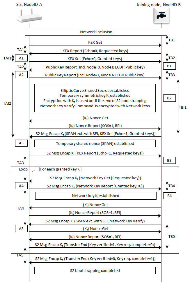
Figure 4.19 S2 bootstrapping frame flow
\requirement{CC:009F.01.00.11.056}{0}
The key exchange MUST comply with the following steps:
Network inclusion completed:
\requirement{CC:009F.01.00.11.057}{4}
Immediately following a successful network inclusion or after receiving an Inclusion Controller Initiate Command (refer to Section 5.2.1.2), the Security 2 enabled controller A MUST start the S2 bootstrapping
A → B: KEX Get:
Including Node A, requests KEX Report from Joining Node B.
B → A: KEX Report:
Sent as response to the KEX Get command, this command contains:
Scheme Report - Schemes supported by Node B
Curve Report - Elliptic Curves supported by Node B
Requested Key List - List of Keys (such as S2 Class keys and Security 0 Network Key) which is requested by Node B
Request for Client-Side authentication
A1:
\requirement{CC:009F.01.00.11.058}{0}
Node A MUST verify the KEX Report and, if required, cancel the S2 bootstrapping as described in Section 4.2.6.6.4.1.
\requirement{CC:009F.01.00.13.007}{0} \requirement{CC:009F.01.00.11.059}{4}
Optional: Node A MAY present a dialog allowing the installer to select which specific keys will be granted to Node B. If presented, the installer MUST either confirm a list of granted keys or cancel the security bootstrapping.
\requirement{CC:009F.01.00.11.0B5}{4}
If Client-Side authentication is requested and Node A supports inclusion using CSA, Node A MUST present a dialog asking if Client-Side authentication should be allowed.
\requirement{CC:009F.01.00.11.05B}{0}
If Client-Side authentication is used, Node A MUST subsequently present a dialog with its own DSK.
\requirement{CC:009F.01.00.13.016}{0} \requirement{CC:009F.01.00.11.093}{4}
Node A MAY reject Client-Side authentication. In this case, Node A MUST either abort the S2 bootstrapping with a KEX_FAIL_CANCEL or only grant a subset of keys that does not require CSA, e.g. Security 0 and Unauthenticated.
A → B: KEX Set:
\requirement{CC:009F.01.00.13.008}{0}
The KEX Set Command contains parameters selected by Node A. The list of class keys MAY be reduced to a subset of the list that was requested in the previous KEX Report from Node B.
Scheme Set - The selected Scheme by Node A for bootstrapping
Curve Set - The selected Curve by Node A for bootstrapping
Key List Set - The list of granted keys to Node B by Node A
Client-Side authentication - Indicating whether Client-side authentication will be used
B1:
\requirement{CC:009F.01.00.11.05D}{0}
Node B MUST verify the KEX Set command and, if required, cancel security bootstrapping as described in Section 4.2.6.6.4.1.
\requirement{CC:009F.01.00.13.009}{0} \requirement{CC:009F.01.00.11.05E}{4} \requirement{CC:009F.01.00.13.00A}{8}
Optional: Node B MAY present the Node A’s DSK for verification or input. If presented, installer MUST either confirm or cancel security bootstrapping. This step MAY also be carried out in step B2 instead is CSA is used.
\requirement{CC:009F.01.00.11.092}{0}
Node B MUST accept what it has been granted, even if it is only a subset of what was requested.
\requirement{CC:009F.01.00.11.091}{0}
If Node A wrongfully grants CSA without being requested, Node B MUST cancel security bootstrapping.
B → A: Public Key B:
Public Key B is the ECDH Public Key of Node B and is used for the ECDH Key Exchange.
If Authentication is required (KEX Set granted an Authenticated Security Class):
\requirement{CC:009F.01.00.11.0BC}{0}
Node B MUST use its Authenticated ECDH Public key and the DSK bytes 1..2 MUST be obfuscated by zeros.
If Authenticated is not required (KEX Set granted no authenticated Security Class):
Node B MUST use its Unauthenticated ECDH Public Key and transmit the full key non-obfuscated.
A2:
\requirement{CC:009F.01.00.11.05F}{0}
If authentication is required, Node A MUST request that the user enters the PIN code or scans the QR code from Node B in order to verify the DSK (refer to Section 4.2.6.6.2 and Section 4.2.6.6.4.1).
If Node A was input a PIN code, it MUST substitute the bytes 1 and 2 of the Node B public key with the 2 bytes received in the PIN code. The user MUST be prompted a dialog to visually validate the bytes 3..16 of Node B’s DSK.
If Node A has received the 16 bytes DSK of Node B via QR scanning, it MUST substitute the first 16 bytes of Node B’s Public Key with the 16 bytes received via QR code.
\requirement{CC:009F.01.00.12.012}{0}
Node A SHOULD continue verifying the DSK input until A3 to allow ECDH calculations to take place while the user is verifying the DSK.
A → B: Public Key A:
Public Key A is the Elliptic Curve Public Key of Node A and will be used for the temporary ECDH Key Exchange.
Mandatory: If Client-Side authentication is used, the DSK bytes 1..4 MUST be obfuscated by zeros.
B2:
Mandatory: If Client-Side authentication is used, the DSK MUST be input on Node B.
If Node B was input a PIN code, it MUST substitute the 4 first bytes of Node A’s Public Key with the 4 bytes received in the PIN code. The user MAY be prompted a dialog to visually validate the bytes 5..16 of Node A’s DSK.
If Node B has received the 16 bytes DSK of Node A via QR scanning, it MUST substitute the first 16 bytes of Node A’s Public Key with the 16 bytes received via QR code
Elliptic Curve Shared Secret Established:
If B2 is passed, Node A and Node B have performed an ECDH Key Exchange, resulting in an Elliptic Curve Shared Secret.
Temporary Symmetric Key Established:
Both Node A and Node B derive a Temporary Symmetric Key from the ECDH Shared Secret based on CKDF-TempExpand (refer to Section 4.2.6.4.8.2).
B → A: Nonce Get:
Node B requests a Nonce from Node A that will allow Node B to send messages securely using the Temporary Symmetric Key.
A → B: Nonce Report:
A’s Nonce
\requirement{CC:009F.01.00.11.062}{0}
From this point all frames sent between Node A and Node B MUST be encrypted using the ECDH Temporary Symmetric Key (With the exception of Nonce Get / Report for each Security Class which MUST NOT be encrypted and the Network Key Verify Command, which MUST be encrypted with the most recently exchanged key. Refer to Section 4.2.6.6.1).
B → A: KEX Set (echo):
The KEX Set command received from Node A in step 5 is confirmed via the temporary secure channel.
\requirement{CC:009F.01.00.11.097}{0}
The frame MUST be retransmitted by node B every 10 seconds for 240 seconds in total until either event is detected:
Step 17, KEX Report(Echo) is received
KEX Fail is received
If neither events are detected after 240 seconds, Node B times out and aborts S2 bootstrapping silently
A3:
\requirement{CC:009F.01.00.11.063}{0}
Node A MUST abort S2 bootstrapping if the KEX Set(Echo) received in step 16 is not identical to KEX Set previously sent by Node A in step 5. Refer to Section 4.2.6.6.4.1.
A → B: KEX Report (echo):
The KEX Report Command received from Node B in step 3 is confirmed via the temporary secure channel.
B3:
\requirement{CC:009F.01.00.11.064}{0}
Node B MUST abort S2 bootstrapping if the KEX Report(Echo) received in step 18 is not identical to KEX Report previously sent by Node B in step 3. Refer to Section 4.2.6.6.4.1.
\requirement{CC:009F.01.00.11.098}{0}
If a Node B node has been granted zero keys, Node B MUST go to step 30 and indicate to Node A that it is terminating the bootstrapping process by returning an S2 Transfer End Command. Node A and Node B will consider Node B to be included non-securely at the end of the bootstrapping.
\requirement{CC:009F.01.00.11.065}{0}
Authentication has been completed, and network key exchange begins. Steps 20 through 29 MUST be repeated for each network key Node A has granted. Key Exchange MUST follow the order described in Section 4.2.6.6.1.
B → A: Security 2 Network Key Get:
Node B requests a specific Key from Node A.
A4:
\requirement{CC:009F.01.00.11.0B2}{0}
Node A MUST cancel the S2 bootstrapping if the requested key is not in the Key List granted by Node A.
A → B: Security 2 Network Key Report:
This command returns the requested key.
B4:
\requirement{CC:009F.01.00.11.094}{0}
Node B MUST cancel security bootstrapping if the received key was not requested. Refer to Section 4.2.6.6.4.1.
\requirement{CC:009F.01.00.11.067}{0}
After receiving the key, Node B MUST perform key derivation as described in Section 4.2.6.4.8.4.
Security 2 Network Key Established:
Node A and Node B are now in possession of a shared network key.
B → A: Nonce Get:
Node B requests a Nonce from Node A that will allow Node B to send messages securely using the recently exchanged Network Key.
A → B: Nonce Report:
A’s Nonce
B → A: Security 2 Network Key Verify:
\requirement{CC:009F.01.00.11.095}{0}
This command MUST be sent encrypted by Node B with the newly received Network Key and the recently established SPAN for this key.
A5:
\requirement{CC:009F.01.00.11.06A}{0}
Node A MUST verify that it can successfully decrypt the Key Verify command using the newly exchanged key.
A → B: Security 2 Transfer End:
\requirement{CC:009F.01.00.11.06B}{0}
If Node A is able to decrypt and verify the Key Verify command, it MUST respond with Security 2 Transfer End with the field “Key verified” set to ‘1’.
If there are more granted keys to request, Node B continues to step 20 and requests the next granted key
If it was the last granted key, Node B continues to step 30.
All Keys have been requested.
B → A: Security 2 Transfer End:
\requirement{CC:009F.01.00.11.06C}{0}
When Node B has no more keys to request it MUST finish the secure setup by sending a Security 2 Transfer End command with the field “Key Request Complete” set to ‘1’.
If this frame is received before all keys have been requested, the controller MUST consider the S2 Bootstrapping process failed.
\requirement{CC:009F.01.00.11.06D}{0}
All timeouts described in Section 4.2.6.6.4.2 MUST be implemented. If a node times out, it MUST silently abort the S2 bootstrapping.
4.2.6.6.4.1. Security 2 bootstrapping Interrupt Points
\requirement{CC:009F.01.00.11.077}{0}
The including node and the joining node MUST interrupt the Security 2 bootstrapping process if any of the events outlined in Table 4.15 occur.
Including Node Interrupts, A1-5 |
|||
Name |
Interrupt Reason |
KEX Fail Command Encryption |
KEX Fail Type (see description in :numref:`security_2_kex_fail_kex_fail_type`) |
A1 |
Key list is invalid or unsupported KEX Scheme is invalid or unsupported Curves are invalid or unsupported User rejects the requested keys |
None |
KEX_FAIL_KEX_KEY KEX_FAIL_KEX_SCHEME KEX_FAIL_KEX_CURVES KEX_FAIL_CANCEL |
A2 |
User cancelled the bootstrapping |
None |
KEX_FAIL_CANCEL |
A3 |
KEX Set(Echo) is not identical to the previous KEX Set |
Temp. Key |
KEX_FAIL_AUTH KEX_FAIL_DECRYPT |
A4 |
The requested Key was not granted in the original KEX set |
Temp. Key |
KEX_FAIL_KEY_GET |
A5 |
The Key Verify Command cannot be decrypted using the most recent key |
Temp. Key |
KEX_FAIL_KEY_VERIFY |
Joining Node Interrupts, B1-4 |
|||
Name |
Interrupt Reason |
KEX Fail Command Encryption |
KEX Fail Type (see description in :numref:`security_2_kex_fail_kex_fail_type`) |
B1 |
Key list is invalid or unsupported KEX Scheme is invalid or unsupported Curves are invalid or unsupported Node A wrongfully grants CSA |
None |
KEX_FAIL_KEX_KEY KEX_FAIL_KEX_SCHEME KEX_FAIL_KEX_CURVES KEX_FAIL_KEX_KEY |
B2 |
If using CSA, user cancelled the bootstrapping |
- |
KEX_FAIL_CANCEL |
B3 |
KEX Report(Echo) is not identical to the previous KEX Report |
Temp. Key |
KEX_FAIL_AUTH KEX_FAIL_DECRYPT |
B4 |
The assigned key was never requested |
Temp. Key |
KEX_FAIL_KEY_REPORT |
\requirement{CC:009F.01.00.12.018}{0}
An aborted Security 2 bootstrapping process due to one of the interrupt points in Table 4.15 SHOULD be followed by a Security 2 KEX Fail Command sent to the other party of the S2 bootstrapping.
\requirement{CC:009F.01.00.11.0A8}{0}
If sent, encryption MUST be used according to Table 4.15.
\requirement{CC:009F.01.00.12.019}{8}
If a command is received using a Security level (non-secure, encrypted with temporary or network key) whereas the command had to be sent encrypted using another Security level, the receiving node SHOULD return a Security 2 KEX Fail Command with the KEX_FAIL_AUTH Fail Type encrypted using the received security level.
\requirement{CC:009F.01.00.11.07C}{0}
In any case, a node MUST NOT return any error indication if no S2 bootstrapping process is currently ongoing.
4.2.6.6.4.2. Security 2 bootstrapping Timeouts
\requirement{CC:009F.01.00.11.07D}{0}
The including Node or the joining node MUST apply timeouts according to Table 4.16.
Including Node Timers, TA1-7 |
||
Name |
Interrupt Reason |
Timeout (Seconds) |
TA1 |
\requirementNS{CC:009F.01.00.11.07E}{0} KEX Report MUST be received after sending KEX Get |
10 |
TA2 |
\requirementNS{CC:009F.01.00.11.07F}{0} Public Key Report MUST be received after sending KEX Set |
10 |
TA3 |
\requirementNS{CC:009F.01.00.11.082}{0} S2 Network Key Get MUST be received after sending KEX Report(Echo) |
10 |
TA4 |
\requirementNS{CC:009F.01.00.11.083}{0} S2 Network Key Verify MUST be received after sending S2 Network Key Report |
10 |
TA5 |
\requirementNS{CC:009F.01.00.11.084}{0} S2 Transfer End OR S2 Network Key Get MUST be received after sending S2 Transfer End |
10 |
TAI1 |
\requirementNS{CC:009F.01.00.13.012}{0} User MAY change Key List for Advanced Joining mode |
240 |
TAI2 |
\requirementNS{CC:009F.01.00.11.085}{0} User MUST have verified/input the DSK |
240 |
Joining Node Timers, TB1-7 |
||
Name |
Interrupt Reason |
Timeout (Seconds) |
TB1 |
\requirementNS{CC:009F.01.00.11.0B3}{0} KEX Get MUST be received after non-secure inclusion |
10..30 for nodes supporting S0 30 for nodes supporting S2 only |
TB2 |
\requirementNS{CC:009F.01.00.11.087}{0} KEX Set MUST be received after sending KEX Report |
240 |
TB3 |
\requirementNS{CC:009F.01.00.11.088}{0} Public Key Report MUST be received after sending Public Key Report |
10 |
TB4 |
\requirementNS{CC:009F.01.00.11.08B}{0} S2 Network Key Report MUST be received after sending S2 Network Key Get |
10 |
TB5 |
\requirementNS{CC:009F.01.00.11.08C}{0} S2 Transfer End MUST be received after sending S2 Network Key Verify |
10 |
TBI1 |
\requirementNS{CC:009F.01.00.11.0AE}{0} If Client-Side Authentication is used, the user MUST have verified/input the DSK |
240 |
\requirement{CC:009F.01.00.11.0AF}{0}
10 seconds timeouts MUST be observed with a 2 seconds tolerance. In this case, a node MUST time out between 8 and 12 seconds.
\requirement{CC:009F.01.00.11.0B0}{0}
30 seconds timeouts MUST be observed with a 5 seconds tolerance. In this case, a node MUST time out between 25 and 35 seconds.
\requirement{CC:009F.01.00.11.0B1}{0}
240 seconds timeouts MUST be observed with a 10 seconds tolerance. In this case, a node MUST time out between 230 and 250 seconds.
4.2.6.7. Security 2 Key Exchange commands
4.2.6.7.1. Security 2 KEX Get Command
This command is used by an including node to query the joining node for supported KEX Schemes and ECDH profiles as well as which network keys the joining node intends to request.
\requirement{CC:009F.01.04.11.001}{0}
This command MUST be ignored if Learn Mode is disabled.
\requirement{CC:009F.01.04.11.002}{0}
The KEX Report Command MUST be returned in response to this command if Learn Mode is enabled.
\requirement{CC:009F.01.04.11.003}{0}
This command MUST NOT be issued via multicast addressing.
\requirement{CC:009F.01.04.11.004}{0}
A receiving node MUST NOT return a response if this command is received via multicast addressing. The Z-Wave Multicast frame, the broadcast NodeID and the Multi Channel multi-End Point destination are all considered multicast addressing methods.
7 |
6 |
5 |
4 |
3 |
2 |
1 |
0 |
|---|---|---|---|---|---|---|---|
Command Class = COMMAND_CLASS_SECURITY_2 (0x9F) |
|||||||
Command = KEX_GET (0x04) |
|||||||
4.2.6.7.2. Security 2 KEX Report Command
This command is used for two purposes during the key exchange:
This command is used by a joining node to advertise the network keys which it intends to request from the including node. The including node subsequently grants keys which may be exchanged once a temporary secure channel has been established.
After establishment of the temporary secure channel, the including node uses this command to confirm the set of keys that the joining node intends to request.
\requirement{CC:009F.01.05.11.003}{0}
A receiving node MUST ignore this command if Add Node mode is not enabled.
7 |
6 |
5 |
4 |
3 |
2 |
1 |
0 |
|---|---|---|---|---|---|---|---|
Command Class = COMMAND_CLASS_SECURITY_2 (0x9F) |
|||||||
Command = KEX_REPORT (0x05) |
|||||||
Reserved |
Request CSA |
Echo |
|||||
Supported KEX Schemes |
|||||||
Supported ECDH Profiles |
|||||||
Requested Keys |
|||||||
Reserved
\requirement{CC:009F.01.05.11.004}{0}
This field MUST be set to 0 by a sending node and MUST be ignored by a receiving node.
Echo (1 bit)
\requirement{CC:009F.01.05.11.005}{0}
If this flag is set to ‘1’, the fields of this command MUST be a copy of the KEX Report received prior to the establishment of the temporary secure channel. All fields described in this section MUST be included in the echo. For the purpose of echoing only, reserved set bits and the reserved field MUST NOT be ignored or set to zero, but MUST be echoed back as received. If future versions of this Command Class append fields to the KEX Report, those fields MUST be omitted from the echo.
\requirement{CC:009F.01.05.11.006}{0}
If this flag is set to ‘1’, the command MUST be sent securely via the temporary secure channel, i.e. encrypted using the TempKeyCCM and TempPersonalizationString.
\requirement{CC:009F.01.05.11.007}{0}
The including node MUST NOT set this flag to ‘0’ when sending this command and MUST ignore this command if this flag is set to ‘1’ when received.
\requirement{CC:009F.01.05.11.008}{0}
The including node MUST return a KEX Set Command in response to this command if the “Echo” flag is set to ‘0’ and is performing S2 Bootstrapping.
\requirement{CC:009F.01.05.11.009}{0}
The joining node MUST NOT set this flag to ‘1’ when sending this command and MUST ignore this command if this flag is set to ‘0’ when received.
Request CSA (1 bit)
If this flag is set, the joining node is requesting the use of Client-side Authentication (CSA).
\requirement{CC:009F.01.05.11.019}{0}
This flag MUST be set to 0 if none of the S2 Authenticated and S2 Access Control Security Classes are requested
\requirement{CC:009F.01.05.11.01A}{0}
This flag MUST be set to 0 if the sending node has a DSK label printed on itself.
\requirement{CC:009F.01.05.11.01B}{0}
This flag MUST be set to 1 by a node only if it has been OTA firmware upgraded to support S2 and requests S2 Authenticated or S2 Access Control Security Class.
Supported KEX Schemes (1 byte)
This field is used to advertise the KEX Schemes supported by the node.
The field MUST be treated as a bitmask and MUST comply with the format indicated in Table 4.17:
Bit |
KEX Scheme |
Description |
|---|---|---|
0, 2..7 |
Reserved |
Reserved |
1 |
KEX Scheme 1 |
Indicates if Scheme 1 is supported (Security 2 Class Keys 0..2) |
All other bits are reserved and MUST be set to zero by a sending node.
\requirement{CC:009F.01.05.11.00E}{0}
If the KEX scheme is supported the corresponding bit MUST be set to ‘1’.
If the KEX scheme is not supported the corresponding bit MUST be set to ‘0’.
\requirement{CC:009F.01.05.11.00F}{0}
A node supported the Security 2 Command Class MUST support KEX Scheme 1.
Supported ECDH Profiles (1 byte)
This field is used to advertise the supported ECDH Profiles by the joining node
\requirement{CC:009F.01.05.11.010}{0}
The field MUST be treated as a bitmask and MUST comply with the format indicated in Table 4.18:
Bit |
ECDH Profile |
KEX Scheme |
Public Key Length |
|---|---|---|---|
0 |
Curve25519 |
Indicates support for Curve25519 [1] |
32 Bytes |
All other bits are reserved and MUST be set to zero by a sending node.
\requirement{CC:009F.01.05.11.013}{0}
If the ECDH Profile is supported the corresponding bit MUST be set to ‘1’
If the ECDH Profile is not supported the corresponding bit MUST be set to ‘0’
\requirement{CC:009F.01.05.11.014}{0}
Curve25519 MUST be supported by a node supporting the Security 2 Command Class.
Requested Keys (1 byte)
This field is used by a joining node to advertise the keys that the manufacturer finds most appropriate for the actual type of product.
\requirement{CC:009F.01.05.13.001}{0}
The joining node MAY request a subset of the keys defined in Table 4.19.
\requirement{CC:009F.01.05.11.015}{0}
The field MUST be treated as a bitmask and MUST comply with the format indicated in Table 4.19:
Security Level (1 highest - 4 lowest) |
Bit |
KEX Scheme |
Key |
Indicates support for |
|---|---|---|---|---|
1 |
2 |
KEX Scheme 1 |
S2.2 |
S2 Access Control Class |
2 |
1 |
KEX Scheme 1 |
S2.1 |
S2 Authenticated Class |
3 |
0 |
KEX Scheme 1 |
S2.0 |
S2 Unauthenticated Class |
4 |
7 |
KEX Scheme 1 |
S0 |
S0 Secure legacy devices |
All other bits are reserved and MUST be set to zero by a sending node. Reserved bits MUST be ignored by a receiving node.
\requirement{CC:009F.01.05.11.017}{0}
If the Key is requested the corresponding bit MUST be set to ‘1’.
If the Key is not requested the corresponding bit MUST be set to ‘0’.
\requirement{CC:009F.01.05.11.018}{0}
A node supporting the Security 2 Command Class MUST support at least one Key. A node may support multiple keys.
4.2.6.7.3. Security 2 KEX Set Command
This command is used for two purposes:
During initial key exchange this command is used by an including node to grant network keys to a joining node. The joining node subsequently requests the granted keys once a temporary secure channel has been established.
\requirement{CC:009F.01.06.11.001}{0}
The including node MUST send the command non-securely.
After establishment of the temporary secure channel, the joining node issues this command to the including node to securely state its intention to request the keys that were granted previously.
\requirement{CC:009F.01.06.11.002}{0}
The joining node MUST send the command securely via the temporary secure channel, i.e. encapsulated using the
TempKeyCCMandTempPersonalizationString.
\requirement{CC:009F.01.06.11.003}{0}
This command MUST be ignored if Learn mode and Add Node mode are both disabled.
\requirement{CC:009F.01.06.11.004}{0}
The including node MUST return the Security 2 KEX Report Command in response to this command unless it is to be ignored.
\requirement{CC:009F.01.06.11.005}{0}
This command MUST NOT be issued via multicast addressing.
\requirement{CC:009F.01.06.11.006}{0}
A receiving node MUST NOT return a response if this command is received via multicast addressing. The Z-Wave Multicast frame, the broadcast NodeID and the Multi Channel multi-End Point destination are all considered multicast addressing methods.
7 |
6 |
5 |
4 |
3 |
2 |
1 |
0 |
|---|---|---|---|---|---|---|---|
Command Class = COMMAND_CLASS_SECURITY_2 (0x9F) |
|||||||
Command = KEX_SET (0x06) |
|||||||
Reserved |
Request CSA |
Echo |
|||||
Supported KEX Schemes |
|||||||
Supported ECDH Profile |
|||||||
Granted Keys |
|||||||
Reserved
\requirement{CC:009F.01.06.11.007}{0}
This field MUST be set to 0 by a sending node and MUST be ignored by a receiving node.
Echo (1 bit)
\requirement{CC:009F.01.06.11.008}{0}
If this flag is set to ‘1’, the fields of this command MUST be an identical copy of the KEX Set Command received prior to the establishment of the temporary secure channel.
\requirement{CC:009F.01.06.11.009}{0}
The joining node MUST set this flag to ‘1’.
\requirement{CC:009F.01.06.11.00A}{0}
The including node MUST abort the S2 bootstrapping if it receives a KEX Set Command with this flag set to ‘0’.
\requirement{CC:009F.01.06.11.00B}{0}
If the “Echo” flag is set to ‘1’ and the Add Node mode is enabled, the including node MUST return a KEX Report Command with the “Echo” flat set to ‘1’ in response to this command.
\requirement{CC:009F.01.06.11.00D}{0}
The including node MUST set this flag to ‘0’.
\requirement{CC:009F.01.06.11.00E}{0}
The joining node MUST abort the S2 bootstrapping if it receives a KEX Set Command with this flag set to ‘1’.
Request CSA (1 bit)
If this flag is set to ‘1’, the including node is permitting the use of Client-side Authentication (CSA).
Selected KEX Scheme (1 byte)
\requirement{CC:009F.01.06.11.010}{0}
This field is used to specify the Scheme that the including node is granting to the joining node. Exactly one bit MUST be set to ‘1’. Reserved bits MUST be examined for the purpose of verifying that exactly one bit is set. Several bits set MUST trigger an error as indicated in Section 4.2.6.6.4.1.
For field format, refer to Table 4.17.
Selected ECDH Profile (1 byte)
\requirement{CC:009F.01.06.11.011}{0}
This field specifies the ECDH Profile selected by the including node for ECDH Key Exchange. The field MUST carry exactly one of the bits listed in Table 4.18. Reserved bits MUST be examined for the purpose of verifying that exactly one bit is set.
For field format, refer to Table 4.18.
Granted Keys (1 byte)
\requirement{CC:009F.01.06.11.012}{0}
If the Echo field is set to ‘0’, this field MUST specify the keys which the including node is granting to the joining node.
\requirement{CC:009F.01.06.11.013}{0}
The value of this field MUST be the same set or a subset of the Requested Keys field advertised in the KEX Report by the joining node during initial S2 bootstrapping.
\requirement{CC:009F.01.06.11.014}{0}
If the Echo field is set to ‘1’, this field MUST advertise the keys which the including node granted to the joining node in the previous KEX Set Command sent by the including node to the joining node.
For field format, refer to Table 4.19.
\requirement{CC:009F.01.06.11.015}{0}
A joining node MUST NOT issue Network Key Get requests for keys that are not specified in this field.
\requirement{CC:009F.01.06.11.016}{0}
An including node MUST return a Security 2 KEX Fail Command and abort S2 bootstrapping if it subsequently receives a Network Key Get request for keys that are not specified in this field.
4.2.6.7.4. Security 2 KEX Fail Command
This command is used to advertise an error condition to the other party of am S2 bootstrapping process.
The interrupt points that may trigger the transmission of this command are defined in Section 4.2.6.2.4.2.
\requirement{CC:009F.01.07.11.001}{0}
This command MUST be ignored if Learn mode and Add Node mode are both disabled.
7 |
6 |
5 |
4 |
3 |
2 |
1 |
0 |
|---|---|---|---|---|---|---|---|
Command Class = COMMAND_CLASS_SECURITY_2 (0x9F) |
|||||||
Command = KEX_FAIL (0x07) |
|||||||
KEX Fail Type |
|||||||
KEX Fail Type (1 byte)
This field MUST advertise one of the types defined in Table 4.20.
Value |
KEX Fail Type Identifier |
Description |
|---|---|---|
0x01 |
KEX_FAIL_KEX_KEY |
Key failure indicating that no match exists between requested/granted keys in the network. |
0x02 |
KEX_FAIL_KEX_SCHEME |
Scheme failure indicating that no scheme is supported by controller or joining node specified an invalid scheme. |
0x03 |
KEX_FAIL_KEX_CURVES |
Curve failure indicating that no curve is supported by controller or joining node specified an invalid curve. |
0x05 |
KEX_FAIL_DECRYPT |
Node failed to decrypt received frame. |
0x06 |
KEX_FAIL_CANCEL |
User has cancelled the S2 bootstrapping. |
0x07 |
KEX_FAIL_AUTH |
The Echo KEX Set/Report frame did not match the earlier exchanged frame. A command is received using the wrong Security level. |
0x08 |
KEX_FAIL_KEY_GET |
The joining node has requested a key, which was not granted by the including node at an earlier stage. |
0x09 |
KEX_FAIL_KEY_VERIFY |
Including node failed to decrypt and hence verify the received frame encrypted with exchanged key. |
0x0A |
KEX_FAIL_KEY_REPORT |
The including node has transmitted a frame containing a different key than what is currently being exchanged. |
4.2.6.7.5. Security 2 Public Key Report Command
This command is used by both the including and the joining node to establish the Elliptic Curve Shared Secret. This is needed to establish the temporary secure channel that enables transfer of all other keys.
\requirement{CC:009F.01.08.11.001}{0}
This command MUST be ignored if Learn mode and Add Node mode are both disabled.
7
6
5
4
3
2
1
0
Command Class = COMMAND_CLASS_SECURITY_2 (0x9F)
Command = PUBLIC_KEY_REPORT (0x08)
Reserved
Including Node
ECDH Public Key 1 (MSB)
…
ECDH Public Key N (LSB)
Reserved
\requirement{CC:009F.01.08.11.002}{0}
This field MUST be set to 0 by a sending node and MUST be ignored by a receiving node.
Including Node (1 bit)
The Including Node flag advertises if the sending node is the including node or the joining node.
\requirement{CC:009F.01.08.11.003}{0}
When sent by the including node this flag MUST be set to ‘1’.
\requirement{CC:009F.01.08.11.004}{0}
The joining node MUST abort S2 bootstrapping if this flag is set to ‘0’ in a received command.
\requirement{CC:009F.01.08.11.005}{0}
When sent by the joining node this flag MUST be set to ‘0’.
\requirement{CC:009F.01.08.11.006}{0}
The including node MUST abort S2 bootstrapping if this flag is set to ‘1’ in a received command.
ECDH Public Key (N bytes)
Device Specific ECDH Public Key of the sending node.
\requirement{CC:009F.01.08.11.007}{0}
The public key MUST be unique for each node. The length of this field is determined by the chosen ECDH profile. Refer to Table 4.18.
\requirement{CC:009F.01.08.11.008}{0}
If Controller-Side Authentication is used, the DSK bytes 1..2 MUST be obfuscated with zeros (0x00) by the joining node
If Client-Side Authentication (CSA) is used, the DSK bytes 1..4 MUST be obfuscated with zeros (0x00) by the including node.
\requirement{CC:009F.01.08.11.00B}{4}
If no authentication is used (S2 Unauthenticated and/or S0 classes are granted only), both joining and including nodes ECDH Public Keys MUST be transmitted in their integrality
4.2.6.7.6. Security 2 Network Key Get Command
\requirement{CC:009F.01.09.11.001}{4}
This command is used by a joining node to request one key from the including node. One instance of this command MUST be sent for each key that was granted by the including node.
\requirement{CC:009F.01.09.11.002}{0}
The command MUST be sent security encapsulated using the TempKeyCCM and TempPersonalizationString.
\requirement{CC:009F.01.09.11.003}{0}
This command MUST be ignored unless the Add Node mode is enabled.
\requirement{CC:009F.01.09.11.004}{0}
The Security 2 Network Key Report Command MUST be returned in response to this command unless this command is ignored.
\requirement{CC:009F.01.09.11.005}{0}
This command MUST NOT be issued via multicast addressing.
\requirement{CC:009F.01.09.11.006}{0}
A receiving node MUST NOT return a response if this command is received via multicast addressing. The Z-Wave Multicast frame, the broadcast NodeID and the Multi Channel multi-End Point destination are all considered multicast addressing methods.
7 |
6 |
5 |
4 |
3 |
2 |
1 |
0 |
|---|---|---|---|---|---|---|---|
Command Class = COMMAND_CLASS_SECURITY_2 (0x9F) |
|||||||
Command = SECURITY_2_NETWORK_KEY_GET (0x09) |
|||||||
Requested Key |
|||||||
Requested Key (1 byte)
This field is used to request a network key.
\requirement{CC:009F.01.09.11.007}{0}
Only one key MUST be requested at a time, i.e. only 1 bit MUST be set to ‘1’. This field MUST be encoded according to Table 4.19.
4.2.6.7.7. Security 2 Network Key Report Command
This command is used by an including node to transfer one key to the joining node.
\requirement{CC:009F.01.0A.11.001}{0}
The command MUST be sent security encapsulated using the TempKeyCCM and TempPersonalizationString.
\requirement{CC:009F.01.0A.11.002}{0}
This command MUST be ignored unless the Learn mode is enabled.
\requirement{CC:009F.01.0A.11.003}{0}
The joining node MUST store the received network key in non-volatile memory.
7 |
6 |
5 |
4 |
3 |
2 |
1 |
0 |
|---|---|---|---|---|---|---|---|
Command Class = COMMAND_CLASS_SECURITY_2 (0x9F) |
|||||||
Command = SECURITY_2_NETWORK_KEY_REPORT (0x0A) |
|||||||
Granted Key |
|||||||
Network Key byte 1 |
|||||||
… |
|||||||
Network Key byte 16 |
|||||||
Granted Key (1 byte)
\requirement{CC:009F.01.0A.11.004}{0}
This field is used to indicate which Network Key is carried in the command and MUST be encoded according to Table 4.19.
Network Key (16 bytes)
This field carries the granted Network Key.
4.2.6.7.8. Security 2 Network Key Verify Command
This command is used by a joining node to verify a newly exchanged key with the including node.
\requirement{CC:009F.01.0B.11.007}{0}
This command MUST be sent security encapsulated using the Key that was just exchanged and MUST be encrypted using the derived KeyCCM and PersonalizationString.
\requirement{CC:009F.01.0B.11.004}{0}
The Security 2 Transfer End Command MUST be returned in response to this command unless it is to be ignored.
\requirement{CC:009F.01.0B.11.005}{0}
The joining node MUST NOT consider the actual key exchange to be complete until a Security 2 Transfer End command has been received from the including node.
\requirement{CC:009F.01.0B.11.006}{0}
This command MUST be ignored if Learn mode and Add Node mode are both disabled.
7 |
6 |
5 |
4 |
3 |
2 |
1 |
0 |
|---|---|---|---|---|---|---|---|
Command Class = COMMAND_CLASS_SECURITY_2 (0x9F) |
|||||||
Command = SECURITY_2_NETWORK_KEY_VERIFY (0x0B) |
|||||||
4.2.6.7.9. Security 2 Transfer End Command
This command is used by the including node to complete the verification of each individual key exchange while the joining node uses this command to complete the S2 bootstrapping process after all granted keys have been successfully exchanged.
\requirement{CC:009F.01.0C.11.001}{0}
The joining node MUST send this command after all granted keys have been verified.
\requirement{CC:009F.01.0C.11.002}{0}
This command MUST be ignored if Learn mode and Add Node mode are both disabled.
7 |
6 |
5 |
4 |
3 |
2 |
1 |
0 |
|---|---|---|---|---|---|---|---|
Command Class = COMMAND_CLASS_SECURITY_2 (0x9F) |
|||||||
Command = SECURITY_2_TRANSFER_END (0x0C) |
|||||||
Reserved |
Key Verified |
Key Request Complete |
|||||
Reserved
\requirement{CC:009F.01.0C.11.003}{0}
This field MUST be set to 0 by a sending node and MUST be ignored by a receiving node.
Key Verified (1 bit)
\requirement{CC:009F.01.0C.11.004}{0}
The including node MUST set this flag to ‘1’ if it has successfully verified the Key Verify Command using the newly exchanged network key.
\requirement{CC:009F.01.0C.11.005}{0}
This flag MUST be set to ‘0’ in all other cases.
\requirement{CC:009F.01.0C.11.009}{0}
If this field is set to 0, a receiving node MUST abort S2 bootstrapping and consider that S2 bootstrapping process failed.
Key Request Complete (1 bit)
\requirement{CC:009F.01.0C.11.006}{0}
The joining node MUST set this flag to ‘1’ if it has completed exchanging all granted keys.
\requirement{CC:009F.01.0C.11.007}{0}
This flag MUST be set to ‘0’ in all other cases.
\requirement{CC:009F.01.0C.11.008}{0}
The including node MUST consider S2 bootstrapping to be successfully completed if it receives this command with this flag set to ‘1’ and all keys have been exchanged.
4.2.6.8. Discovery of Security Capabilities Commands
A controlling node may discover the Command Class capabilities of a securely included node.
\requirement{CC:009F.01.00.13.015}{0}
The advertised capabilities MAY depend on the actual security level used to request capabilities.
Likewise, the advertised capabilities at a given security level may depend on the S2 bootstrapping security level.
4.2.6.8.1. Security 2 Commands Supported Get Command
This command is used to query the command classes that a joining node supports via secure communication.
\requirement{CC:009F.01.0D.11.001}{0}
Security 2 encryption MUST be used when transmitting this command.
\requirement{CC:009F.01.0D.11.002}{0}
The Security 2 Commands Supported Report Command MUST be returned in response to this command. The response MUST be sent encrypted, using the same Security 2 Class key and encapsulation as was used for this command.
\requirement{CC:009F.01.0D.11.003}{0}
A node receiving this command on its highest granted Security Class MUST respond with the Security 2 Commands Supported Report Command containing all supported secure command classes.
\requirement{CC:009F.01.0D.11.004}{0}
A node receiving this command on any other Security Class than its highest granted Security Class MUST respond with the Security 2 Commands Supported Report Command containing no command classes.
\requirement{CC:009F.01.0D.11.007}{0}
A node receiving the Security Commands Supported Get of the (non S2) Security 0 Command Class (using S0 key and S0 Message Encapsulation Command), MUST respond with the Security 0 Commands Supported Report containing no command classes.
\requirement{CC:009F.01.0D.11.006}{0}
This command MUST NOT be issued via multicast addressing.
A receiving node MUST NOT return a response if this command is received via multicast addressing. The Z-Wave Multicast frame, the broadcast NodeID and the Multi Channel multi-End Point destination are all considered multicast addressing methods.
7 |
6 |
5 |
4 |
3 |
2 |
1 |
0 |
|---|---|---|---|---|---|---|---|
Command Class = COMMAND_CLASS_SECURITY_2 (0x9F) |
|||||||
Command = SECURITY_2_COMMANDS_SUPPORTED_GET (0x0D) |
|||||||
4.2.6.8.2. Security 2 Commands Supported Report Command
\requirement{CC:009F.01.0E.11.001}{4}
This command is used to advertise the commands that a joining node supports via secure communication. Security 2 encryption MUST be used when transmitting this command.
\requirement{CC:009F.01.0E.11.002}{0}
Transport Service segmentation MUST be used if the command is longer than the available payload length of a single Z-Wave MAC frame.
7 |
6 |
5 |
4 |
3 |
2 |
1 |
0 |
|---|---|---|---|---|---|---|---|
Command Class = COMMAND_CLASS_SECURITY_2 (0x9F) |
|||||||
Command = SECURITY_2_COMMANDS_SUPPORTED_REPORT (0x0E) |
|||||||
Command Class 1 |
|||||||
… |
|||||||
Command Class N |
|||||||
\requirement{CC:009F.01.0E.11.003}{0} \requirement{CC:009F.01.0E.12.001}{4}
This command MUST NOT advertise command classes that the joining node can control in other nodes. Network management user interfaces SHOULD discover control capabilities of a node via the Association Group Information (AGI) Command Class.
As per Section 4.2.6.6, a node may be assigned up to four keys for the S2 Unauthenticated, S2 Authenticated, S2 Access Control and S0 Classes, respectively.
For instance, a light dimmer may accept non-securely transmitted commands if it is not S2 bootstrapped, while the same dimmer will require secure communication for commands if it is S2 bootstrapped. This allows a Security 2 enabled light dimmer to be compatible with first-generation non-secure Z-Wave networks while it will operate fully secure when included in a S2 network at a later time.
In another example, a door lock may be designed to work only with the S0 network key or the S2 Access Control Class key. Inclusion in a network without security bootstrapping will not allow operation of the lock and if bootstrapped with the S2 Access Control Class, S0 encrypted commands will also be ignored.
\requirement{CC:009F.01.0E.11.00F}{0}
The Security 0 and Security 2 Command Class MUST NOT be advertised in this command
The Transport Service Command Class MUST NOT be advertised in this command.
\requirement{CC:009F.01.0E.13.002}{0}
A sending node MAY terminate the list of supported command classes with the COMMAND_CLASS_MARK command class identifier.
\requirement{CC:009F.01.0E.11.007}{0}
A receiving node MUST stop parsing the list of supported command classes if it detects the COMMAND_CLASS_MARK command class identifier in the Security 2 Commands Supported Report.
Command Class (N bytes)
This field advertises the command classes that the node supports.
\requirement{CC:009F.01.0E.11.008}{0}
A normal Command Class identifier MUST be one byte long in the range (0x20-0xEE). An extended Command Class identifier MUST be two bytes long where the first byte is in the range (0xF1-0xFF), while the second byte is in the range 0x00-0xFF.
\requirement{CC:009F.01.0E.13.003}{0}
A joining node MAY advertise extended command classes.
\requirement{CC:009F.01.0E.11.009}{0}
An including node MUST accept extended command classes.