5.2.5. Network Management Command Class, version 1
5.2.5.1. Compatibility considerations
\requirement{CC:0000.00.00.21.001}{4}
The commands defined in the following sections may span more than the available payload length in Z-Wave frames. If the command payload does not fit in a single frame, commands MUST be fragmented using the Transport Service Command Class.
\requirement{CC:0000.00.00.21.002}{0}
When using IP transport, the IP UDP data segment length limit of 1280 bytes MUST be respected.
\requirement{CC:0000.00.00.22.001}{8}
There is a risk that a controlling node would try to issue Network Management commands to a controller which does not support functionality due to its Network role (i.e. Secondary controller). A controller SHOULD adjust its NIF (or S0/S2 Commands Supported Report Command) based on its network role after inclusion.
\requirement{CC:0000.00.00.21.004}{0}
When a node has the SIS, Primary controller or Inclusion controller role, it MUST support:
Network Management Inclusion Command Class
Network Management Basic Command Class
Transport Service Command Class
\requirement{CC:0000.00.00.21.005}{0}
When a node has the secondary controller role, it MUST support:
Network Management Basic Command Class
The Z-Wave Network Management commands are organized as follows
Command Class |
Purpose |
|---|---|
Network Management Proxy |
The command class is used to report the list of nodes present in a Z-Wave Network and report the secure/non-secure capabilities of each of those nodes Version 2 of this command class extends the node capability reporting to Multi Channel End Points. |
Network Management Basic Node |
The command class is used to remotely control network management operations related to including supporting nodes into a Z-Wave network. The available functionalities are :
Version 2 of this command class extends the learn mode activation commands In order to support S2 and adds the following functionality:
|
Command Class |
Purpose |
|---|---|
Network Management Inclusion |
This command class is used to remotely control network management operations related to including other nodes into a Z-Wave network. The available functionalities are :
Version 2 of this command class extends the Add/Remove/Replace commands to support S2 and adds the following functionality:
|
Network Management Primary |
This command class is used to remotely trigger a controller change operation. |
Network Management Installation and maintenance |
This command class is used for maintenance and optimization purposes. The available functionalities are :
|
5.2.5.1.1. Sequence number management
The following text applies to all sequence numbers used by Network Management Command Classes.
\requirement{CC:0000.00.00.21.006}{0}
Each sequence number MUST be generated from an 8-bit counter that is incremented by 1 whenever a new sequence number is generated. When a node powers up, the sequence counter MUST be initialized to a random value.
\requirement{CC:0000.00.00.23.001}{0}
All command classes referring to this section MAY use the same global counter.
\requirement{CC:0000.00.00.21.007}{0}
When responding to a request command, a responding node MUST echo the sequence number used by the requesting node.
\requirement{CC:0000.00.00.21.008}{0}
When receiving response to a request command, the requesting node MUST verify that the response carries the same sequence number as the request command.
5.2.5.2. Scope of network management
Network management commands may be used in a number of scenarios. Three scopes have been identified:
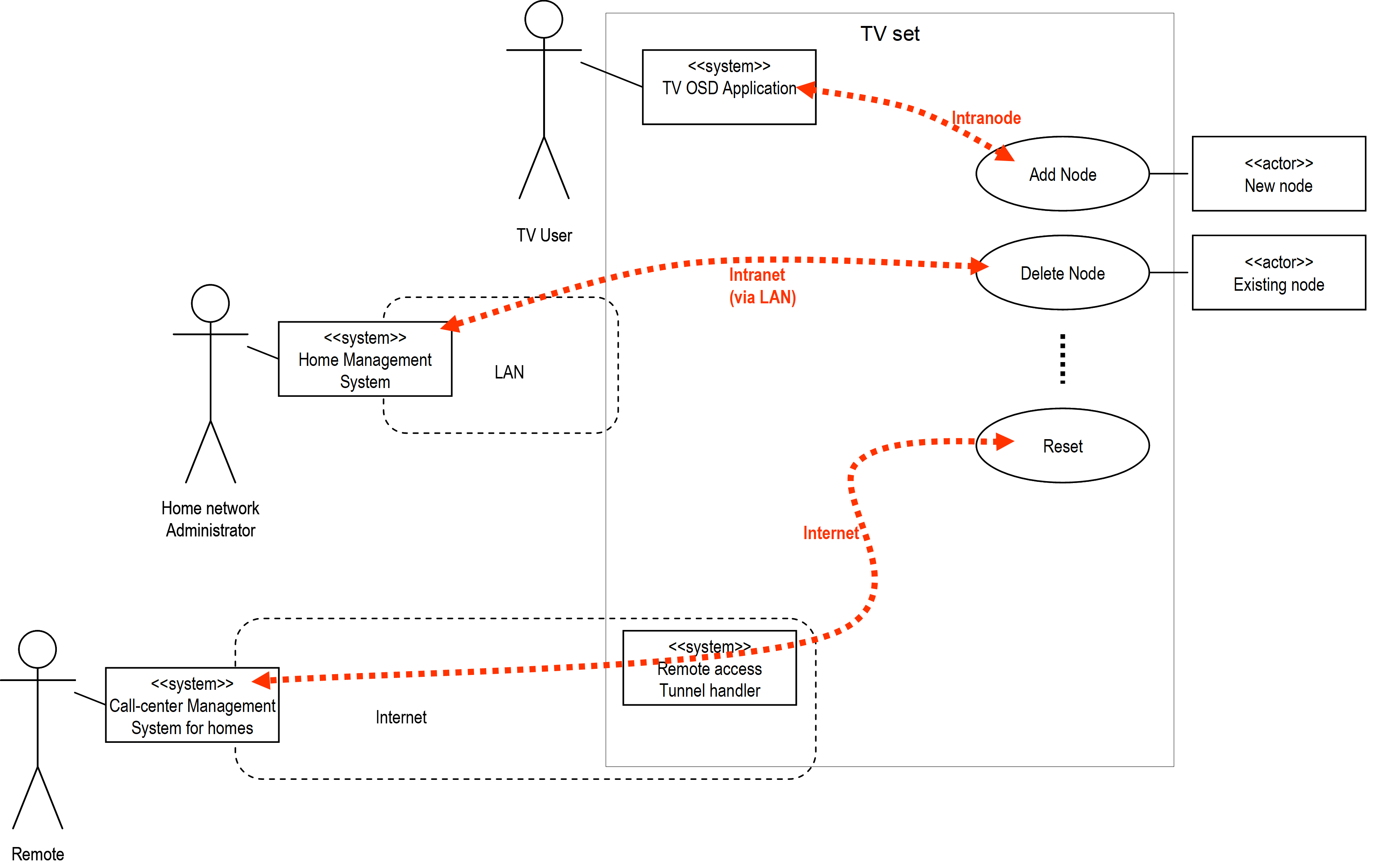
Figure 5.11 Scope of network management
5.2.5.2.1. Intranode
When used in an intranode configuration, the network management command classes are primarily used for implementation convenience. As an example, a software module of the Z/IP Gateway application may be used to provide a standard IP-based interface for other Linux applications inside a set-top box. In this way an application programmer does not have to bother about serial port communication, Telnet command parsing, etc.
5.2.5.2.2. Intranet (LAN)
Managed building automation systems may implement one central network manager controlling a number of geographically distributed Z/IP Gateways via the network management command classes. Each Z/IP Gateway may be instructed to perform local inclusion or exclusion of nodes; thus creating a large infrastructure segmented into subnets.
5.2.5.2.3. Internet (WAN)
The help desk of a service provider may provide support from a remote call center via the Internet. This enables the deployment of border routers, remote controls and plug-in modules in consumer environments without relying on the technical interest and/or capabilities of the user.
5.2.5.3. Security considerations
\requirement{CC:0000.00.00.42.001}{0}
Network management is a powerful toolbox. From an application level, it SHOULD be ensured that the user does not unintentionally reset the controller or remove nodes.
\requirement{CC:0000.00.00.41.001}{0}
At the same time it MUST be ensured that it is not possible for unauthorized persons to inject malicious commands into the network, e.g. resetting the primary controller to default factory settings.
\requirement{CC:0000.00.00.41.002}{0}
All Network Management Command Class MUST be sent securely when used on a Z-Wave network, using at least Z-Wave Security 0 Command Class, version 1. When used on the LAN side other means of security should be used.
If the network management commands are carried in IP packets over Z-Wave, a minimum level of security is automatically applied since S0 network security is mandatory for all Z/IP traffic.
\requirement{CC:0000.00.00.42.002}{0}
When Z-Wave network management commands are carried over IP LAN and WAN media (intranet & internet) the IP traffic SHOULD be using secure communication. A Z/IP Gateway MAY allow a LAN-based IP host to send un encrypted Network Management commands to a controller via the Z/IP Gateway. Support for un encrypted Network Management commands SHOULD be disabled by default and after a factory reset.
5.2.5.3.1. Designing for single-threading and limited transmit buffer
\requirement{CC:0000.00.00.41.003}{4}
In order to support constrained CPU platforms, the Z-Wave API has been designed for single-threaded operation. A node MUST ignore Network Management command if already processing or executing another Network Management command.
\requirement{CC:0000.00.00.42.003}{0}
A node SHOULD NOT ignore the command if it is identical to the command currently being processed/executed (e.g. Add Node Command with mode: Stop when Add Mode is active)
\requirement{CC:0000.00.00.41.004}{0}
A node MUST return status messages to the node that actually initiated the operation.
\requirement{CC:0000.00.00.41.005}{0} \requirement{CC:0000.00.00.42.004}{4}
An controlling node MUST time out waiting for a status message. The time out SHOULD depend on the actual command. If not receiving a status message within the defined time out for a command, the node SHOULD re-send the Network Management command using the same sequence number to allow the target node to detect duplicates.
\requirement{CC:0000.00.00.43.001}{0}
A receiving node MAY return a ”busy” indication. Doing so could however lead to transmit buffer overflows. Care should be taken to avoid this during implementation.
\requirement{CC:0000.00.00.41.006}{4}
The Z-Wave Ack does not necessarily indicate that the command is being executed, but that it has been received by the protocol. The sending application MUST wait for the Network Management command callback, or time out.
5.2.5.4. Network management proxy command class, version 1
The Network Management Proxy Command Class provides functions to access basic network information such as the list of nodes currently present in the Z-Wave network.
5.2.5.4.1. Node list get command
This command is used to request the network node list from local storage in a node.
\requirement{CC:0052.01.01.11.001}{0}
The Node List Report Command MUST be returned in response to this command.
\requirement{CC:0052.01.01.11.002}{0}
This command MUST NOT be issued via multicast addressing.
\requirement{CC:0052.01.01.11.003}{4}
A receiving node MUST NOT return a response if this command is received via multicast addressing. The Z-Wave Multicast frame, the broadcast NodeID and the Multi Channel multi-End Point destination are all considered multicast addressing methods.
7 |
6 |
5 |
4 |
3 |
2 |
1 |
0 |
|---|---|---|---|---|---|---|---|
Command Class = COMMAND_CLASS_NETWORK_MANAGEMENT_PROXY (0x52) |
|||||||
Command = NODE_LIST_GET (0x01) |
|||||||
Seq No |
|||||||
Seq No (1 byte)
Refer to Sequence number management.
5.2.5.4.2. Node list report command
This command carries node data requested with the Node List Get Command.
\requirement{CC:0052.01.02.11.001}{4} \requirement{CC:0052.01.02.12.001}{8}
In addition, when a node has been added to or removed from the network or when the Z/IP Gateway has acquired the SIS role, the Z/IP Gateway MUST send an unsolicited Node List Report with the new network information to the unsolicited destination.
\requirement{CC:0052.01.02.11.002}{0}
If the unsolicited destination itself has initiated the node addition or removal, this command SHOULD NOT be sent.
\requirement{CC:0052.01.02.11.004}{0}
The Z/IP Gateway MAY send an unsolicited Node List Report when it is ready after power reset. If no unsolicited destination has been set, the gateway MUST NOT send a Node List Report upon network changes.
7 |
6 |
5 |
4 |
3 |
2 |
1 |
0 |
|---|---|---|---|---|---|---|---|
Command Class = COMMAND_CLASS_NETWORK_MANAGEMENT_PROXY (0x52) |
|||||||
Command = NODE_LIST_REPORT (0x02) |
|||||||
Seq No |
|||||||
Status |
|||||||
Node List Controller ID |
|||||||
Node List Data 1 |
|||||||
… |
|||||||
Node List Data 29 |
|||||||
Seq No 1byte)
Refer to Sequence number management.
Status 8 bits)
\requirement{CC:0052.01.02.11.003}{0}
This field indicates the status of Node List data carried in the command. The field MUST take one of the following values:
0x00: The Node List Data contains the latest updated node list.
0x01: The Node List Data may be outdated.
Node List Controller ID (1 byte)
The Node List Controller ID is a NodeID pointing at a controller, which keeps latest updated node list. The value 0x00 indicates that Node List Controller ID is unknown.
\requirement{CC:0052.01.02.12.002}{0}
The Node List Controller SHOULD provide up-to-date information, but the actual freshness of data depends on the network construction. If a portable controller is primary there may be no access to the most recent network data. In that case the user may have to manually wake up the portable controller and initiate a controller replication to an always listening secondary controller.
No explicit Z-Wave route is provided for reaching the Node List Controller. The requesting node may use methods such as explorer discovery or Controller Network Update if the node does not already hold a working route to the indicated Node List Controller.
The Node List Controller ID may not support Network Management Proxy Command Class.
Node List Data (29 bytes)
This field carries a complete bitmap presenting all included nodes as a set bit (‘1’) while unused NodeIDs are presented as a (‘0’). The first bit in the bitmap represents NodeID 1; the last bit represents NodeID 232.
A receiving node can use the Node Info Cached Get Command to get information on individual node properties.
5.2.5.4.3. Node info cached get command
This command is used to request node capabilities that have been cached by another node. The command works as a proxy function provided by the node list controller. The purpose is to preserve the bandwidth of the Z-Wave network and to provide access to properties of sleeping nodes.
\requirement{CC:0052.01.03.11.001}{0}
The Node Info Cached Report Command MUST be returned in response to this command.
\requirement{CC:0052.01.03.13.001}{0} \requirement{CC:0052.01.03.11.002}{4}
A Z/IP client MAY issue the Node Info Cached Get command as an IPv4 broadcast or an IPv6 ‘all routers’ multicast packet. A Z/IP Gateway MUST accept such a packet and return a Node Info Cached Report in response.
\requirement{CC:0052.01.03.11.003}{0}
A Node Info Cached Report returned by a Z/IP Gateway in response to an IP multicast packet MUST be delayed by a random delay in the range 0..450msec as more than one Z/IP Gateway may be responding.
\requirement{CC:0052.01.03.11.004}{0}
The Z/IP Gateway MUST respond to an IP multicast by returning a unicast IP packet.
\requirement{CC:0052.01.03.13.002}{0}
A Z/IP Client MAY time out waiting for Node Info Cached Report commands after 500msec.
7 |
6 |
5 |
4 |
3 |
2 |
1 |
0 |
|---|---|---|---|---|---|---|---|
Command Class = COMMAND_CLASS_NETWORK_MANAGEMENT_PROXY (0x52) |
|||||||
Command = NODE_INFO_CACHED_GET (0x03) |
|||||||
Seq No |
|||||||
Reserved |
Max Age |
||||||
NodeID |
|||||||
Seq No (1 byte)
Refer to Sequence number management.
Reserved
\requirement{CC:0052.01.03.11.005}{0}
This field MUST be set to 0 by a sending node and MUST be ignored by a receiving node.
Max Age (4 bits)
\requirement{CC:0052.01.03.12.001}{4}
The maximum age of the Node Info frame, given in 2^n minutes. If the cache entry does not exist or if it is older that the value given in this field, the Z/IP Gateway SHOULD attempt to get a fresh Node Info Frame before responding to this command.
A value of 15 means infinite, i.e. No Cache Refresh. A value of 0 means force update. The values 1..15 allow for cache timeouts in the range 2min, 4min, …, 11days – and infinite.
NodeID (1 byte)
\requirement{CC:0052.01.03.11.006}{0}
This field MUST indicate the NodeID for which the receiving node is to return cached data.
The value 0x00 MUST be interpreted as the ID of the queried network management node.
5.2.5.4.4. Node info cached report command
This command is used for returning cached node information.
7 |
6 |
5 |
4 |
3 |
2 |
1 |
0 |
|---|---|---|---|---|---|---|---|
Command Class = COMMAND_CLASS_NETWORK_MANAGEMENT_PROXY (0x52) |
|||||||
Command = NODE_INFO_CACHED_REPORT (0x04) |
|||||||
Seq No |
|||||||
Status |
Age |
||||||
List. |
Z-Wave Protocol Specific Part |
||||||
Opt. Func. |
Z-Wave Protocol Specific Part |
||||||
Reserved |
|||||||
Basic Device Class |
|||||||
Generic Device Class |
|||||||
Specific Device Class |
|||||||
Command Class 1 *) |
|||||||
… |
|||||||
Command Class N *) |
|||||||
*) Command classes may be extended –> spanning two bytes for one command class
Seq No (1 byte)
Refer to Sequence number management.
Status (4 bits)
\requirement{CC:0052.01.04.11.001}{4}
This field is used to indicate the Node Info Cached information status. This field MUST comply with Table 5.25.
Value |
Status identifier |
Description |
|---|---|---|
0x00 |
STATUS_OK |
The requested NodeID could be found and up-to-date information is returned. |
0x01 |
STATUS_NOT_RESPONDING |
The requested NodeID could be found but fresh information could not be retrieved. |
0x02 |
STATUS_UNKNOWN |
The NodeID is unknown. |
Age (4 bits)
\requirement{CC:0052.01.04.11.002}{4}
This field indicates the age of the Node Info frame, i.e. the time elapsed since the data has been received by the actual node. This field MUST be expressed in ”2^n minutes”. This field’s value MUST be rounded down, i.e.12 minutes MUST be reported as 2^3 = 8 minutes and not as 2^4 = 16 min.
List (1 bit)
The Optional Functionality bit indicates if true ( == ‘1’) the node supports more command classes in addition to the ones covered by the device classes listed in this message. The additional command classes follow the device class fields.
Reserved
\requirement{CC:0052.01.04.11.003}{0}
This field MUST be set to 0 by a sending node and MUST be ignored by a receiving node.
Z-Wave Protocol Specific Part
\requirement{CC:0052.01.04.11.004}{0}
This field is the protocol specific part of the NIF. It MUST be set as received in the Node Information Frame.
Basic Device Class (1 byte)
This field indicates the Basic Device Class of the actual node.
Generic Device Class (1 byte)
This field indicates the Generic Device Class of the actual node. The Generic Device Classes for Z-Wave Plus are listed in [35] and Section 7.
Specific Device Class (1 byte)
This field indicates the Specific Device Class of the actual node. The Specific Device Classes for Z-Wave Plus are listed in [35] and Section 7.
Command Class (N bytes)
This field indicates the command classes implemented by the actual node.
\requirement{CC:0052.01.04.11.005}{0}
The Security Scheme 0 Mark MUST be used to delimit Command Classes available non-securely and securely.
\requirement{CC:0052.01.04.11.006}{0}
The Support/Control Mark MUST be used before and after the Security Scheme 0 Mark if it was present in the node’s NIF.
\requirement{CC:0052.01.04.11.007}{0}
A Command Class field structure example is shown in Table 5.26. The field MUST comply with Table 5.27.
Description |
Command Class field content |
|||||||
|---|---|---|---|---|---|---|---|---|
… |
7 |
6 |
5 |
4 |
3 |
2 |
1 |
0 |
Non-secure Supported Command Classes |
Command Class 1 *) |
|||||||
Non-secure Supported Command Classes |
… |
|||||||
Non-secure Supported Command Classes |
Command Class M *) |
|||||||
Support/Control Mark |
0xEF |
|||||||
Non-secure Controlled Command Classes |
Command Class 1 *) |
|||||||
Non-secure Controlled Command Classes |
… |
|||||||
Non-secure Controlled Command Classes |
Command Class K *) |
|||||||
Security Scheme 0 Mark |
0xF1 |
|||||||
Security Scheme 0 Mark |
0x00 |
|||||||
S0 Secure Supported Command Classes |
Command Class 1 *) |
|||||||
S0 Secure Supported Command Classes |
… |
|||||||
S0 Secure Supported Command Classes |
Command Class L *) |
|||||||
Support/Control Mark |
0xEF |
|||||||
S0 Secure Controlled Command Classes |
Command Class 1 *) |
|||||||
S0 Secure Controlled Command Classes |
… |
|||||||
S0 Secure Controlled Command Classes |
Command Class P *) |
|||||||
*) Command classes may be extended –> spanning two bytes for one command class
Command Class ID |
Description |
|---|---|
0x20..0xEE |
Command Class identifier |
0xF101..0xFFFF |
Extended Command Classes identifier |
0xEF |
Command Class Support/Control Mark Anything between this mark and the next mark is Controlled and not supported |
0xF100 |
Security Scheme 0 Command Class Mark. Command Classes following this Mark are supported or controlled with Security Scheme 0 |
5.2.5.5. Network management proxy command class, version 2
5.2.5.5.1. Compatibility considerations
\requirement{CC:0052.02.00.21.001}{4}
The Network Management Proxy Command Class, version 2 is backwards compatible with Network Management Proxy Command Class, version 1. A node supporting Network Management Proxy Command Class, version 2 MUST also support Network Management Proxy Command Class, version 1.
All commands not mentioned in this version remain unchanged from version 1.
The following command has been extended to support S2 bootstrapping information:
Node Info Cached Report
The following commands have been added to support Multi Channel End Point probing:
Network Management Multi Channel End Point Get Command
Network Management Multi Channel End Point Report Command
Network Management Multi Channel Capability Get Command
Network Management Multi Channel Capability Report Command
Network Management Multi Channel Aggregated Members Get Command
Network Management Multi Channel Aggregated Members Report Command
5.2.5.5.2. Node info cached report command
This command is used for returning cached node information.
7 |
6 |
5 |
4 |
3 |
2 |
1 |
0 |
|---|---|---|---|---|---|---|---|
Command Class = COMMAND_CLASS_NETWORK_MANAGEMENT_PROXY (0x52) |
|||||||
Command = NODE_INFO_CACHED_REPORT (0x04) |
|||||||
Seq No |
|||||||
Status |
Age |
||||||
List. |
Z-Wave Protocol Specific Part |
||||||
Opt. Func. |
Z-Wave Protocol Specific Part |
||||||
Granted Keys |
|||||||
Basic Device Class |
|||||||
Generic Device Class |
|||||||
Specific Device Class |
|||||||
Command Class 1 *) |
|||||||
… |
|||||||
Command Class N *) |
|||||||
*) Command classes may be extended –> spanning two bytes for one command class
Fields not described in this version remain unchanged from version 1.
Granted Keys (8 bits)
\requirement{CC:0052.02.04.11.001}{4}
This field is used to indicate which network keys were granted during bootstrapping. This field MUST be treated as a bitmask and comply with Table 5.85
Command Class (N bytes)
Refer to Section 5.2.5.4.4 and Table 5.27.
\requirement{CC:0052.02.04.11.002}{0}
The Security Command Class Mark (0xF100) MUST indicate command classes supported using the highest listed Security Key in the Granted Key field value.
5.2.5.5.3. Network management multi channel end point get command
This command is used to query the number of Multi Channel End Points and other relevant Multi Channel attributes.
\requirement{CC:0052.02.05.11.001}{0}
The Network Management Multi Channel End Point Report Command MUST be returned in response to this command unless it is to be ignored.
7 |
6 |
5 |
4 |
3 |
2 |
1 |
0 |
|---|---|---|---|---|---|---|---|
Command Class = COMMAND_CLASS_NETWORK_MANAGEMENT_PROXY (0x52) |
|||||||
Command = NM_MULTI_CHANNEL_END_POINT_GET (0x05) |
|||||||
Seq No |
|||||||
NodeID |
|||||||
Seq No (1 byte)
Refer to Sequence number management.
NodeID (1 byte)
\requirement{CC:0052.02.05.11.002}{0}
This field MUST indicate the NodeID for which the receiving node is to return cached data. If the specified NodeID does not exist, this command MUST be ignored.
5.2.5.5.4. Network management multi channel end point report command
This command is used to advertise the number of Multi Channel End Points implemented by a node.
7 |
6 |
5 |
4 |
3 |
2 |
1 |
0 |
|---|---|---|---|---|---|---|---|
Command Class = COMMAND_CLASS_NETWORK_MANAGEMENT_PROXY (0x52) |
|||||||
Command = NM_MULTI_CHANNEL_END_POINT_REPORT (0x06) |
|||||||
Seq No |
|||||||
NodeID |
|||||||
Reserved |
|||||||
Res |
Individual End Points |
||||||
Res |
Aggregated End Points |
||||||
Seq No (1 byte)
Refer to Sequence number management.
NodeID (1 byte)
\requirement{CC:0052.02.06.11.001}{0}
This field MUST indicate the NodeID for which the receiving node is to return cached data.
Reserved / Res
\requirement{CC:0052.02.06.11.002}{0}
This field MUST be set to 0 by a sending node and MUST be ignored by a receiving node.
Individual End Points (7 bits)
\requirement{CC:0052.02.06.11.003}{0}
This field MUST advertise the number of individual End Points implemented by this node.
\requirement{CC:0052.02.06.11.004}{0}
The value MUST be in the range 0..127. The sum of the values advertised by the Individual End Points and Aggregated End Points fields MUST be in the range 0..127.
Aggregated End Points (7 bits)
\requirement{CC:0052.02.06.11.005}{0}
This field MUST advertise the number of Aggregated End Points implemented by this node.
\requirement{CC:0052.02.06.11.006}{0}
The value MUST be in the range 0..127. The sum of the values advertised by the Individual End Points and Aggregated End Points fields MUST be in the range 0..127.
\requirement{CC:0052.02.06.11.007}{0}
If no Aggregated End Points are implemented, this field MUST advertise the value 0 (zero).
5.2.5.5.5. Network management multi channel capability get command
This command is used to query the capabilities of one individual End Point or Aggregated End Point.
\requirement{CC:0052.02.07.11.001}{0}
The Network Management Multi Channel Capability Report Command MUST be returned in response to this command unless it is to be ignored.
7 |
6 |
5 |
4 |
3 |
2 |
1 |
0 |
|---|---|---|---|---|---|---|---|
Command Class = COMMAND_CLASS_NETWORK_MANAGEMENT_PROXY (0x52) |
|||||||
Command = NM_MULTI_CHANNEL_CAPABILITY_GET (0x07) |
|||||||
Seq No |
|||||||
NodeID |
|||||||
Res |
End Point |
||||||
Seq No (1 byte)
Refer to Sequence number management.
NodeID (1 byte)
\requirement{CC:0052.02.07.11.002}{0}
This field MUST indicate the NodeID for which the receiving node is to return cached data.
Res
\requirement{CC:0052.02.07.11.003}{0}
This field MUST be set to 0 by a sending node and MUST be ignored by a receiving node.
End Point (7 bits)
\requirement{CC:0052.02.07.13.001}{0}
This field MAY specify a valid End Point as advertised by the Multi Channel End Point Report. If the specified End Point does not exist, this command MUST be ignored.
5.2.5.5.6. Network management multi channel capability report command
This command is used to advertise the generic and specific device class and the supported command classes of one End Point.
7 |
6 |
5 |
4 |
3 |
2 |
1 |
0 |
|---|---|---|---|---|---|---|---|
Command Class = COMMAND_CLASS_NETWORK_MANAGEMENT_PROXY (0x52) |
|||||||
Command = NM_MULTI_CHANNEL_CAPABILITY_REPORT (0x08) |
|||||||
Seq No |
|||||||
NodeID |
|||||||
Command Class Length |
|||||||
Res |
End Point |
||||||
Generic Device Class |
|||||||
Specific Device Class |
|||||||
Generic Device Class |
|||||||
Specific Device Class |
|||||||
Command Class 1 *) |
|||||||
… |
|||||||
Command Class N *) |
|||||||
*) Command classes may be extended –> spanning two bytes for one command class
Seq No (1 byte)
Refer to Sequence number management.
NodeID (1 byte)
\requirement{CC:0052.02.08.11.001}{0}
This field MUST indicate the NodeID for which the receiving node is to return cached data.
Res (1 bit)
\requirement{CC:0052.02.08.11.002}{0}
This field MUST be set to 0 by a sending node and MUST be ignored by a receiving node.
Command Class Length (1 byte)
\requirement{CC:0052.02.08.11.003}{0}
This field MUST advertise the length in bytes of the Command Class field.
End Point (7 bits)
\requirement{CC:0052.02.08.11.004}{0}
This field MUST advertise a valid End Point as advertised by the Multi Channel End Point Report.
Generic Device class (8 bits)
This field indicates the Generic Device Class of the advertised End Point.
Specific Device class (8 bits)
This field indicates the Specific Device Class of the advertised End Point.
Command Class (N bytes)
\requirement{CC:0052.02.08.11.005}{0}
This field MUST advertise Command Classes supported or controlled by the End Point in question.
Refer to Section 5.2.5.4.4 and Table 5.27.
\requirement{CC:0052.02.08.11.006}{0}
The Security Command Class Mark (0xF100) MUST indicate command classes supported using the highest listed Security Key in the Granted Key field value.
5.2.5.5.7. Network management multi channel aggregated members get command
This command is used to query the members of an Aggregated End Point.
\requirement{CC:0052.02.09.11.001}{0}
The Network Management Multi Channel Aggregated Members Report Command MUST be returned in response to this command unless it is to be ignored.
7 |
6 |
5 |
4 |
3 |
2 |
1 |
0 |
|---|---|---|---|---|---|---|---|
Command Class = COMMAND_CLASS_NETWORK_MANAGEMENT_PROXY (0x52) |
|||||||
Command = NM_MULTI_CHANNEL_AGGREGATED_MEMBERS_GET (0x09) |
|||||||
Seq No |
|||||||
NodeID |
|||||||
Res |
Aggregated End Point |
||||||
Seq No (1 byte)
Refer to Sequence number management.
NodeID (1 byte)
\requirement{CC:0052.02.09.11.002}{0}
This field MUST indicate the NodeID for which the receiving node is to return cached data. This command MUST be ignored if the NodeID field is not valid.
Res
\requirement{CC:0052.02.09.11.003}{0}
This field MUST be set to 0 by a sending node and MUST be ignored by a receiving node.
Aggregated End Point (7 bits)
\requirement{CC:0052.02.09.11.004}{0}
This field MUST specify an Aggregated End Point. This command MUST be ignored if the End Point does not exist or is not an Aggregated End Point.
5.2.5.5.8. Network management multi channel aggregated members report command
This command is used to advertise the members of an Aggregated End Point.
7 |
6 |
5 |
4 |
3 |
2 |
1 |
0 |
|---|---|---|---|---|---|---|---|
Command Class = COMMAND_CLASS_NETWORK_MANAGEMENT_PROXY (0x52) |
|||||||
Command = NM_MULTI_CHANNEL_AGGREGATED_MEMBERS_REPORT (0x0A) |
|||||||
Seq No |
|||||||
NodeID |
|||||||
Res |
Aggregated End Point |
||||||
Number of Members |
|||||||
Res |
Member Endpoint 1 |
||||||
… |
|||||||
Res |
Member Endpoint N |
||||||
Seq No (1 byte)
Refer to Sequence number management.
NodeID (1 byte)
\requirement{CC:0052.02.0A.11.001}{0}
This field MUST indicate the NodeID for which the receiving node is to return cached data.
Res
\requirement{CC:0052.02.0A.11.002}{0}
This field MUST be set to 0 by a sending node and MUST be ignored by a receiving node.
Aggregated End Point (7 bits)
\requirement{CC:0052.02.0A.11.003}{0}
This field MUST advertise an Aggregated End Point.
\requirement{CC:0052.02.0A.11.004}{0}
If the command is returned in response to a Multi Channel Aggregated Members Get, this field MUST advertise the same value as was received in the Multi Channel Aggregated Members Get command.
Number of Members (8 bits)
\requirement{CC:0052.02.0A.11.005}{0}
This field MUST advertise the number of members of the aggregated End Points
Member Endpoint (N * 7 bits)
\requirement{CC:0052.02.0A.11.006}{4}
This list is used to advertise the End Point members of the Aggregated End Point advertised in the Aggregated End Point field. The length of the list MUST be determined from the Number of Members field. This field MUST be omitted if the Number of Members field is set to 0.
\requirement{CC:0052.02.0A.11.007}{0}
Each object in the list is a 7-bit End Point ID. The addressing bit (Res) MUST be set to 0 by a sending node and MUST be ignored by a receiving node.
5.2.5.6. Network management proxy command class, version 3
5.2.5.6.1. Compatibility considerations
The Network Management Proxy Command Class, version 3 is backwards compatible with Network Management Proxy Command Class, version 2.
\requirement{CC:0052.03.00.21.001}{0}
All commands and fields not mentioned in this version MUST remain unchanged from version 1.
The Command Class is extended with these 2 commands:
Failed Node List Get Command
Failed Node List Report Command
The strategy for considering that nodes are failing (or non-responsive/unlikely to respond to frames again) is implementation specific and may differ from one supporting node to another. A controlling node SHOULD allow the Replace Failed Node and Remove Failed node network management functions for nodes reported as failing.
5.2.5.6.2. Failed node list get command
This command is used to request the network node list that is marked as failing (or non-responsive).
\requirement{CC:0052.03.0B.11.001}{0}
The Failed Node List Report Command MUST be returned in response to this command.
\requirement{CC:0052.03.0B.11.002}{0} \requirement{CC:0052.03.0B.11.003}{4}
This command MUST NOT be issued via multicast addressing. A receiving node MUST NOT return a response if this command is received via multicast addressing. The Z-Wave Multicast frame, the broadcast NodeID and the Multi Channel multi-End Point destination are all considered multicast addressing methods.
7 |
6 |
5 |
4 |
3 |
2 |
1 |
0 |
|---|---|---|---|---|---|---|---|
Command Class = COMMAND_CLASS_NETWORK_MANAGEMENT_PROXY (0x52) |
|||||||
Command = FAILED_NODE_LIST_GET (0x0B) |
|||||||
Seq No |
|||||||
Seq No (1 byte)
Refer to Sequence number management.
5.2.5.6.3. Failed node list report command
This command is used to advertise the current list of failing nodes in the network.
7 |
6 |
5 |
4 |
3 |
2 |
1 |
0 |
|---|---|---|---|---|---|---|---|
Command Class = COMMAND_CLASS_NETWORK_MANAGEMENT_PROXY (0x52) |
|||||||
Command = FAILED_NODE_LIST_REPORT (0x0C) |
|||||||
Seq No |
|||||||
Failed Node List Data 1 |
|||||||
… |
|||||||
Failed Node List Data 29 |
|||||||
Seq No (1 byte)
Refer to Sequence number management.
Failed Node List Data (29 bytes)
This field carries a complete bitmask representation of nodes ranging from NodeID 1 to NodeID 232.
\requirement{CC:0052.03.0C.11.001}{0}
Bit 0 in byte 1 MUST represent NodeID 1
Bit 1 in byte 1 MUST represent NodeID 2
…
Bit 7 in byte 29 MUST represent NodeID 232
\requirement{CC:0052.03.0C.11.002}{0}
The value 0 MUST indicate that the NodeID is either not part of the network or part of the network and fully functional.
The value 1 MUST indicate that the NodeID is part of the network and is failing (or not responding to frames)
5.2.5.7. Network management proxy command class, version 4
5.2.5.7.1. Compatibility Considerations
The Network Management Proxy Command Class, version 4 is backwards compatible with Network Management Proxy Command Class, version 3.
All commands and fields not mentioned in this version MUST remain unchanged from version 3.
This version of the Network Management Proxy Command Class introduces support for the Z-Wave Long Range protocol. The following commands are updated:
Node List Report Command
Node Info Cached Get Command
Network Management Multi Channel End Point Get Command
Network Management Multi Channel End Point Report Command
Network Management Multi Channel Capability Get Command
Network Management Multi Channel Capability Report
Network Management Multi Channel Aggregated Members Get Command
Network Management Multi Channel Aggregated Members Report Command
Failed Node List Report Command
5.2.5.7.2. Node list report command
This command is used to advertise the list of nodes in the Z-Wave / Z-Wave Long Range network.
A Z/IP Gateway MAY send an unsolicited Node List Report when it is ready after power reset. If no unsolicited destination has been set, the gateway MUST NOT send a Node List Report upon network changes.
7 |
6 |
5 |
4 |
3 |
2 |
1 |
0 |
|---|---|---|---|---|---|---|---|
Command Class = COMMAND_CLASS_NETWORK_MANAGEMENT_PROXY (0x52) |
|||||||
Command = NODE_LIST_REPORT (0x02) |
|||||||
Seq No |
|||||||
Status |
|||||||
Node List Controller ID |
|||||||
Node List Data 1 |
|||||||
… |
|||||||
Node List Data 29 |
|||||||
Extended Node List Length (MSB) |
|||||||
Extended Node List Length (LSB) |
|||||||
Extended Node List 1 |
|||||||
… |
|||||||
Extended Node List N |
|||||||
All fields not described below MUST remain unchanged from version 3.
Extended Node List Length (2 bytes)
This field is used to advertise the length in byte of the Extended Node List. A sending node SHOULD set this field to the smallest value allowing to advertise all NodeIDs present in the current network.
Extended Node List (N bytes)
This field is used to advertise the list of nodes included in the network with a NodeID greater than 255.
The length of this field (in bytes) MUST be according to the Extended Node List Length field.
This field MUST be treated as a bitmask and encoded as follow.
Bit 0 in byte 1 MUST represent NodeID 256 (0x100)
Bit 1 in byte 1 MUST represent NodeID 257 (0x101)
etc.
The value 0 MUST indicate that no node has the corresponding NodeID assigned in the network. The value 1 MUST indicate there is a node with the corresponding NodeID assigned present in the network.
5.2.5.7.3. Node info cached get command
This command is used to request the capabilities of a node present in the network.
The Node Info Cached Report Command MUST be returned in response to this command.
A Z/IP client MAY issue the Node Info Cached Get command as an IPv4 broadcast or an IPv6 ‘all routers’ multicast packet. A Z/IP Gateway MUST accept such a packet and return a Node Info Cached Report in response.
A Node Info Cached Report returned by a Z/IP Gateway in response to an IP multicast packet MUST be delayed by a random delay in the range 0..450msec as more than one Z/IP Gateway may be responding.
The Z/IP Gateway MUST respond to an IP multicast by returning a unicast IP packet.
A Z/IP Client MAY time out waiting for Node Info Cached Report commands after 500msec.
7 |
6 |
5 |
4 |
3 |
2 |
1 |
0 |
|---|---|---|---|---|---|---|---|
Command Class = COMMAND_CLASS_NETWORK_MANAGEMENT_PROXY (0x52) |
|||||||
Command = NODE_INFO_CACHED_GET (0x03) |
|||||||
Seq No |
|||||||
Reserved |
Max Age |
||||||
NodeID |
|||||||
Extended NodeID (MSB) |
|||||||
Extended NodeID (LSB) |
|||||||
All fields not described below MUST remain unchanged from version 3.
NodeID (1 byte)
This field MUST indicate the NodeID for which the receiving node is to return cached data. The value 0x00 MUST be interpreted as the ID of the queried network management node.
The value 0xFF MUST indicate that the queried NodeID is indicated in the Extended NodeID field.
Extended NodeID (2 bytes)
This field is used to indicate the NodeID for which the Node Information is requested
This field MUST be set to the same value as the NodeID field by a sending node and ignored by a receiving node if the NodeID field value is in the range 0x00..0xFE
This field MUST be used in place of the NodeID if the NodeID field is set to 0xFF.
5.2.5.7.4. Network management multi channel end point get command
This command is used to query the number of Multi Channel End Points and other relevant Multi Channel attributes.
The Network Management Multi Channel End Point Report Command MUST be returned in response to this command unless it is to be ignored.
7 |
6 |
5 |
4 |
3 |
2 |
1 |
0 |
|---|---|---|---|---|---|---|---|
Command Class = COMMAND_CLASS_NETWORK_MANAGEMENT_PROXY (0x52) |
|||||||
Command = NM_MULTI_CHANNEL_END_POINT_GET (0x05) |
|||||||
Seq No |
|||||||
NodeID |
|||||||
Extended NodeID (MSB) |
|||||||
Extended NodeID (LSB) |
|||||||
All fields not described below MUST remain unchanged from version 3.
NodeID (1 byte)
This field MUST indicate the NodeID for which the number of endpoints is requested. If the specified NodeID does not exist, this command MUST be ignored.
If this field is set to 0xFF, it MUST indicate that the NodeID is indicated in the Extended NodeID field.
Extended NodeID (2 bytes)
This field is used to indicate the requested NodeID.
If the NodeID field is in the range 0x00..0xFE, this field MUST be set to the same value as the NodeID field by a sending node.
If the NodeID field is set to 0xFF, this field MUST indicate the NodeID for which the number of endpoints MUST be returned.
If the specified NodeID does not exist, this command MUST be ignored.
5.2.5.7.5. Network management multi channel end point report command
This command is used to advertise the number of Multi Channel End Points implemented by a node.
7 |
6 |
5 |
4 |
3 |
2 |
1 |
0 |
|---|---|---|---|---|---|---|---|
Command Class = COMMAND_CLASS_NETWORK_MANAGEMENT_PROXY (0x52) |
|||||||
Command = NM_MULTI_CHANNEL_END_POINT_REPORT (0x06) |
|||||||
Seq No |
|||||||
NodeID |
|||||||
Reserved |
|||||||
Res |
Individual End Points |
||||||
Res |
Aggregated End Points |
||||||
Extended NodeID (MSB) |
|||||||
Extended NodeID (LSB) |
|||||||
Fields not described below MUST remain unchanged from version 3.
NodeID (1 byte)
This field MUST indicate the NodeID for which the number of endpoints is advertised.
If the specified NodeID does not exist, this command MUST be ignored.
If this field is set to 0xFF, it MUST indicate that the NodeID is indicated in the Extended NodeID field.
Extended NodeID (2 bytes)
This field is used to indicate the advertised NodeID.
If the NodeID field is in the range 0x00..0xFE, this field MUST be set to the same value as the NodeID field by a sending node.
If the NodeID field is set to 0xFF, this field MUST indicate the NodeID for which the number of endpoints is advertised.
5.2.5.7.6. Network management multi channel capability get command
This command is used to query the capabilities of one individual End Point or Aggregated End Point.
The Network Management Multi Channel Capability Report Command MUST be returned in response to this command unless it is to be ignored.
7 |
6 |
5 |
4 |
3 |
2 |
1 |
0 |
|---|---|---|---|---|---|---|---|
Command Class = COMMAND_CLASS_NETWORK_MANAGEMENT_PROXY (0x52) |
|||||||
Command = NM_MULTI_CHANNEL_CAPABILITY_GET (0x07) |
|||||||
Seq No |
|||||||
NodeID |
|||||||
Reserved |
|||||||
Res |
End Point |
||||||
Extended NodeID (MSB) |
|||||||
Extended NodeID (LSB) |
|||||||
Fields not described below MUST remain unchanged from version 3.
NodeID (1 byte)
This field MUST indicate the NodeID for which the capabilities are requested.
If this field is set to 0xFF, it MUST indicate that the NodeID is indicated in the Extended NodeID field.
Extended NodeID (2 bytes)
This field is used to indicate the requested NodeID.
If the NodeID field is in the range 0x00..0xFE, this field MUST be set to the same value as the NodeID field by a sending node.
If the NodeID field is set to 0xFF, this field MUST indicate the NodeID for which the number of endpoints is advertised.
If the specified NodeID does not exist, this command MUST be ignored.
5.2.5.7.7. Network management multi channel capability report command
This command is used to advertise the generic and specific device class and the supported command classes of one End Point.
7 |
6 |
5 |
4 |
3 |
2 |
1 |
0 |
|---|---|---|---|---|---|---|---|
Command Class = COMMAND_CLASS_NETWORK_MANAGEMENT_PROXY (0x52) |
|||||||
Command = NM_MULTI_CHANNEL_CAPABILITY_REPORT (0x08) |
|||||||
Seq No |
|||||||
NodeID |
|||||||
Command Class Length |
|||||||
Res |
End Point |
||||||
Generic Device Class |
|||||||
Specific Device Class |
|||||||
Command Class 1 *) |
|||||||
… |
|||||||
Command Class N *) |
|||||||
Extended NodeID (MSB) |
|||||||
Extended NodeID (LSB) |
|||||||
Fields not described below MUST remain unchanged from version 3.
NodeID (1 byte)
This field MUST indicate the NodeID for which an endpoint’s capabilities are advertised.
If this field is set to 0xFF, it MUST indicate that the NodeID is indicated in the Extended NodeID field.
Extended NodeID (2 bytes)
This field is used to indicate the advertised NodeID for which an endpoint’s capabilities are advertised.
If the NodeID field is in the range 0x00..0xFE, this field MUST be set to the same value as the NodeID field by a sending node.
If the NodeID field is set to 0xFF, this field MUST indicate the NodeID for which an endpoint’s capabilities are advertised.
5.2.5.7.8. Network management multi channel aggregated members get command
This command is used to query the members of an Aggregated End Point.
\requirement{CC:0052.04.09.11.001}{0}
The Network Management Multi Channel Aggregated Members Report Command MUST be returned in response to this command unless it is to be ignored.
7 |
6 |
5 |
4 |
3 |
2 |
1 |
0 |
|---|---|---|---|---|---|---|---|
Command Class = COMMAND_CLASS_NETWORK_MANAGEMENT_PROXY (0x52) |
|||||||
Command = NM_MULTI_CHANNEL_AGGREGATED_MEMBERS_GET (0x09) |
|||||||
Seq No |
|||||||
NodeID |
|||||||
Res |
Aggregated End Point |
||||||
Extended NodeID (MSB) |
|||||||
Extended NodeID (LSB) |
|||||||
Fields not described below MUST remain unchanged from version 3.
NodeID (1 byte)
This field MUST indicate the NodeID for which the aggregated endpoints are requested.
If this field is set to 0xFF, it MUST indicate that the NodeID is indicated in the Extended NodeID field.
Extended NodeID (2 bytes)
This field is used to indicate the requested NodeID.
If the NodeID field is in the range 0x00..0xFE, this field MUST be set to the same value as the NodeID field by a sending node.
If the NodeID field is set to 0xFF, this field MUST indicate the NodeID for which the number of endpoints is advertised.
If the specified NodeID does not exist, this command MUST be ignored.
5.2.5.7.9. Network management multi channel aggregated members report command
This command is used to advertise the members of an Aggregated End Point.
7 |
6 |
5 |
4 |
3 |
2 |
1 |
0 |
|---|---|---|---|---|---|---|---|
Command Class = COMMAND_CLASS_NETWORK_MANAGEMENT_PROXY (0x52) |
|||||||
Command = NM_MULTI_CHANNEL_AGGREGATED_MEMBERS_REPORT (0x0A) |
|||||||
Seq No |
|||||||
NodeID |
|||||||
Res |
Aggregated End Point |
||||||
Number of Members |
|||||||
Res |
Member Endpoint 1 |
||||||
… |
|||||||
Res |
Member Endpoint N |
||||||
Extended NodeID (MSB) |
|||||||
Extended NodeID (LSB) |
|||||||
All fields not described below MUST remain unchanged from version 3.
NodeID (1 byte)
This field MUST indicate the NodeID for which the aggregated endpoint members are advertised.
If this field is set to 0xFF, it MUST indicate that the NodeID is indicated in the Extended NodeID field.
Extended NodeID (2 bytes)
This field is used to indicate the advertised NodeID for which the aggregated endpoint members are advertised.
If the NodeID field is in the range 0x00..0xFE, this field MUST be set to the same value as the NodeID field by a sending node.
If the NodeID field is set to 0xFF, this field MUST indicate the NodeID for which the aggregated endpoint members are advertised.
5.2.5.7.10. Failed node list report command
This command is used to advertise the current list of failing nodes in the network.
7 |
6 |
5 |
4 |
3 |
2 |
1 |
0 |
|---|---|---|---|---|---|---|---|
Command Class = COMMAND_CLASS_NETWORK_MANAGEMENT_PROXY (0x52) |
|||||||
Command = FAILED_NODE_LIST_REPORT (0x0C) |
|||||||
Seq No |
|||||||
Failed Node List Data 1 |
|||||||
… |
|||||||
Failed Node List Data 29 |
|||||||
Extended NodeID (MSB) |
|||||||
Extended NodeID (LSB) |
|||||||
Extended Failed Node List 1 |
|||||||
… |
|||||||
Extended Failed Node List N |
|||||||
All fields not described below MUST remain unchanged from version 3.
Extended Failed Node List Length (2 bytes)
This field is used to advertise the length in byte of the Extended Node List.
A sending node SHOULD set this field to the smallest value allowing to advertise all failed NodeIDs present in the current network.
Extended Failed Node List (N bytes)
This field is used to advertise the list of failing nodes with a NodeID greater than 255.
The length of this field (in bytes) MUST be according to the Extended Failed Node List Length field.
This field MUST be treated as a bitmask and encoded as follow:
Bit 0 in byte 1 MUST represent NodeID 256 (0x100)
Bit 1 in byte 1 MUST represent NodeID 257 (0x101)
etc.
The value 0 MUST indicate that the NodeID is either not part of the network or part of the network and fully functional.
The value 1 MUST indicate that the NodeID is part of the network and is failing (or not responding to frames)
5.2.5.8. Network Management Basic Node Command Class, version 1
5.2.5.8.1. Default set command
This command is used to set the Controller back to the factory default state.
\requirement{CC:004D.01.06.11.001}{0}
The Default Set Complete Command MUST be returned in response to this command. A receiving node MUST return the DEFAULT_SET_BUSY status if it is already busy executing another network management command.
\requirement{CC:004D.01.06.11.002}{0}
This command MUST NOT be issued via multicast addressing.
\requirement{CC:004D.01.06.11.003}{0}
A receiving node MUST ignore this command if it is received via multicast addressing. The Z-Wave Multicast frame, the broadcast NodeID and the Multi Channel multi-End Point destination are all considered multicast addressing methods.
\requirement{CC:004D.01.06.12.001}{0}
This function SHOULD be used with care as it could render a network unusable if the primary controller in an existing network is set back to default. If a node is set to default while it is still a member of a network, the node will become a failing NodeID in that network.
7 |
6 |
5 |
4 |
3 |
2 |
1 |
0 |
|---|---|---|---|---|---|---|---|
Command Class = COMMAND_CLASS_NETWORK_MANAGEMENT_BASIC (0x4D) |
|||||||
Command = DEFAULT_SET (0x06) |
|||||||
Seq No |
|||||||
Seq No (8 bits)
Refer to Sequence number management.
5.2.5.8.2. Default set complete command
This command is used to indicate if the Default Set operation was executed successfully or not.
7 |
6 |
5 |
4 |
3 |
2 |
1 |
0 |
|---|---|---|---|---|---|---|---|
Command Class = COMMAND_CLASS_NETWORK_MANAGEMENT_BASIC (0x4D) |
|||||||
Command = DEFAULT_SET_COMPLETE (0x07) |
|||||||
Seq No |
|||||||
Status |
|||||||
Seq No (8 bits)
Refer to Sequence number management.
Status (8 bits)
\requirement{CC:004D.01.07.11.001}{0}
This field indicates the status of the default set operation. This field MUST comply with Table 5.48.
Value |
Identifier |
Description |
|---|---|---|
0x06 |
DEFAULT_SET_DONE |
The Default Set operation has been completed successfully. |
0x07 |
DEFAULT_SET_BUSY |
The Default Set operation has not been executed because the node is busy. |
5.2.5.8.3. Learn mode set command
This command is used to allow a node to be added to (or removed from) the network. When a node is added to the network, the node is assigned a valid Home ID and NodeID.
This command allows a controlling application to request the transmission of Node Information Frames (NIFs) in regular intervals until included, removed or until learn mode is disabled again.
\requirement{CC:004D.01.01.12.001}{0}
Learn mode SHOULD be enabled only when necessary, and it SHOULD always be disabled again as quickly as possible. However, to ensure a successful synchronization of the inclusion process the device SHOULD be able to stay in learn mode at least 5 seconds.
\requirement{CC:004D.01.01.11.006}{0}
The Learn Mode Set Status Command MUST be returned in response to this command unless it is to be ignored.
\requirement{CC:004D.01.01.11.002}{0}
This command MUST NOT be issued via multicast addressing.
\requirement{CC:004D.01.01.11.003}{0}
A receiving node MUST ignore this command if it is received via multicast addressing. The Z-Wave Multicast frame, the broadcast NodeID and the Multi Channel multi-End Point destination are all considered multicast addressing methods.
7 |
6 |
5 |
4 |
3 |
2 |
1 |
0 |
|---|---|---|---|---|---|---|---|
Command Class = COMMAND_CLASS_NETWORK_MANAGEMENT_BASIC (0x4D) |
|||||||
Command = LEARN_MODE_SET (0x01) |
|||||||
Seq No |
|||||||
Reserved |
|||||||
Mode |
|||||||
Seq No (8 bits)
Refer to Sequence number management.
Reserved
\requirement{CC:004D.01.01.11.004}{0}
This field MUST be set to 0 by a sending node and MUST be ignored by a receiving node.
Mode (8 bits)
\requirement{CC:004D.01.01.11.005}{0}
The Mode field controls operation. This field MUST comply with Table 5.50.
\requirement{CC:004D.01.01.13.001}{16}
Value |
Identifier |
Description |
|---|---|---|
0x00 |
ZW_SET_LEARN_MODE_DISABLE |
Stop the learn mode of the node. The command MAY be ignored if Learn Mode was not activated. The command MAY be ignored if network inclusion or security bootstrapping is ongoing. |
0x01 |
ZW_SET_LEARN_MODE_CLASSIC |
Start the learn mode on the controller and accept only being included in direct range |
0x02 |
ZW_SET_LEARN_MODE_NWI |
Start the learn mode on the controller and accept routed inclusion. |
Examples of Learn Mode activation and deactivation are given in Figure 5.12
5.2.5.8.3.1. Learn mode in a controller
If the receiving node is a controller, it receives and stores the node list and routing table for the network during inclusion. This information transmitted as part of the controller replication. This function will most likely change the capabilities of the controller.
5.2.5.8.4. Learn mode set status command
This command is used to indicate the progress of the Learn Mode Set command.
7 |
6 |
5 |
4 |
3 |
2 |
1 |
0 |
|---|---|---|---|---|---|---|---|
Command Class = COMMAND_CLASS_NETWORK_MANAGEMENT_BASIC (0x4D) |
|||||||
Command = LEARN_MODE_SET_STATUS (0x02) |
|||||||
Seq No |
|||||||
Status |
|||||||
Reserved |
|||||||
New NodeID |
|||||||
Seq No (8 bits)
Refer to Sequence number management.
Status (8 bits)
\requirement{CC:004D.01.02.11.001}{0}
This field indicates the outcome of the learn mode and MUST comply with Table 5.52.
Value |
Identifier |
Description |
|---|---|---|
0x06 |
LEARN_MODE_DONE |
The learn process is complete and the controller is now included into (or excluded from) the network. If the node supports S0 or S2, it indicates that the network inclusion and security bootstrapping were completed successfully (This include the case where the node was granted no S2 key). |
0x07 |
LEARN_MODE_FAILED |
The learn process failed in some general way |
0x09 |
LEARN_MODE_SECURITY_FAILED |
The learn process is complete and the node was included in a network but security bootstrapping failed. The node is not operating securely. |
Reserved
\requirement{CC:004D.01.02.11.002}{0}
This field MUST be set to 0 by a sending node and MUST be ignored by a receiving node.
New NodeID (1 byte)
The NodeID assigned to the new node by another primary controller or inclusion controller.
If the node was removed from the network or if the Status field is different than LEARN_MODE_DONE, this field MUST be set to 0x00.
5.2.5.8.5. Node information send command
This command is used to trigger a receiving node to issue a Node Information Frame (NIF).
\requirement{CC:004D.01.05.11.001}{0}
A node receiving this command MUST send a Node Information Frame to the indicated NodeID with the indicated transmission options. No status message is returned for this command.
\requirement{CC:004D.01.05.13.001}{0} \requirement{CC:004D.01.05.12.001}{4} \requirement{CC:004D.01.05.13.002}{8}
A management application MAY use this message to make a node identify itself towards a Z-Wave remote control during association operations. This command SHOULD NOT be used while learn mode is activated. Instead, periodic Node Information Frame transmissions MAY be enabled along with learn mode; refer to Section 5.2.5.8.1.
7 |
6 |
5 |
4 |
3 |
2 |
1 |
0 |
|---|---|---|---|---|---|---|---|
Command Class = COMMAND_CLASS_NETWORK_MANAGEMENT_BASIC (0x4D) |
|||||||
Command = NODE_INFORMATION_SEND (0x05) |
|||||||
Seq No |
|||||||
Reserved |
|||||||
Destination NodeID |
|||||||
tx Options |
|||||||
Seq No (8 bits)
Refer to Sequence number management.
Reserved
This field MUST be set to 0 by a sending node and MUST be ignored by a receiving node.
Destination NodeID (1 byte)
\requirement{CC:004D.01.05.13.003}{0}
This field indicates the NodeID of the node that will receive the Node Information frame. The NodeID MAY be set to the broadcast NodeID to reach all nodes within direct range.
\requirement{CC:004D.01.05.12.002}{0}
Acknowledgement SHOULD NOT be requested when broadcasting.
tx Options (1 byte)
\requirement{CC:004D.01.05.11.002}{4}
This field allows a management application to specify if the Node Information frame is to be sent with special properties. This field MUST be treated as a bitmask and MUST comply with Table 5.54.
Value |
Option flag identifier |
Description |
|---|---|---|
0x00 |
NULL |
Transmit at normal power level without any transmit options. |
0x01 |
TRANSMIT_OPTION_ACK |
Request acknowledgment from destination node. Allow routing. |
0x02 |
TRANSMIT_OPTION_LOW_POWER |
Transmit at low output power level (1/3 of normal RF range) |
0x10 |
TRANSMIT_OPTION_NO_ROUTE |
Send only in direct range |
0x20 |
TRANSMIT_OPTION_EXPLORE |
Resolve new routes via explorer discovery if existing routes fail |
\requirement{CC:004D.01.05.12.003}{0}
It is RECOMMENDED for a sending node to use the TRANSMIT_OPTION_NO_ROUTE tx Option and the broadcast NodeID in this command.
5.2.5.8.6. Network update request command
This command is used to request network topology updates from the SUC/SIS node.
\requirement{CC:004D.01.03.11.001}{0}
A node MUST NOT use this command if no SUC is present in the network.
The SUC can only handle one network update at a time, so care should be taken not to have multiple controllers in the network ask for updates at the same time.
\requirement{CC:004D.01.03.12.001}{4}
This command will generate a lot of network activity that will use bandwidth and stress the SUC. Therefore, network updates SHOULD be requested as seldom as possible.
\requirement{CC:004D.01.03.11.002}{0}
The Network Update Request Status Command MUST be returned in response to this command.
\requirement{CC:004D.01.03.11.003}{0}
This command MUST NOT be issued via multicast addressing.
\requirement{CC:004D.01.03.11.004}{0}
A receiving node MUST ignore this command if it is received via multicast addressing. The Z-Wave Multicast frame, the broadcast NodeID and the Multi Channel multi-End Point destination are all considered multicast addressing methods.
7 |
6 |
5 |
4 |
3 |
2 |
1 |
0 |
|---|---|---|---|---|---|---|---|
Command Class = COMMAND_CLASS_NETWORK_MANAGEMENT_BASIC (0x4D) |
|||||||
Command = NETWORK_UPDATE_REQUEST (0x03) |
|||||||
Seq No |
|||||||
Seq No (8 bits)
Refer to Sequence number management.
5.2.5.8.7. Network update request status command
This command is used to indicate if the Network Update Request command execution has completed successfully or not.
7 |
6 |
5 |
4 |
3 |
2 |
1 |
0 |
|---|---|---|---|---|---|---|---|
Command Class = COMMAND_CLASS_NETWORK_MANAGEMENT_BASIC (0x4D) |
|||||||
Command = NETWORK_UPDATE_REQUEST (0x03) |
|||||||
Seq No |
|||||||
Status |
|||||||
Seq No (8 bits)
Refer to Sequence number management.
Status (1 byte)
\requirement{CC:004D.01.04.11.001}{0}
This field is used to indicate the status of the Network Update process. This field MUST comply with Table 5.57.
Value |
Status identifier |
Description |
|---|---|---|
0x00 |
ZW_SUC_UPDATE_DONE |
The update process succeeded |
0x01 |
ZW_SUC_UPDATE_ABORT |
The update process aborted because of an error |
0x02 |
ZW_SUC_UPDATE_WAIT |
The SUC node is busy |
0x03 |
ZW_SUC_UPDATE_DISABLED |
The SUC functionality is disabled |
0x04 |
ZW_SUC_UPDATE_OVERFLOW |
The controller requested an update after more than 64 changes have occurred in the network. The controller has to make a replication. |
5.2.5.8.8. Use cases and frame flows
5.2.5.8.8.1. Z/IP client requesting a node to interrupt Learn Mode
The frame flow for interrupting Learn Mode is shown in Figure 5.12.
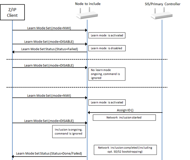
Figure 5.12 Z/IP Client interrupting learn mode
5.2.5.9. Network management basic node command class, version 2
5.2.5.9.1. Compatibility considerations
\requirement{CC:004D.02.00.21.001}{4}
The Network Management Basic Command Class, version 2 is backwards compatible with Network Management Basic Command Class, version 1. A node supporting Network Management Basic Command Class, version 2 MUST also support Network Management Basic Command Class, version 1.
All commands not mentioned in this version remain unchanged from version 1.
The following commands are introduced to allow a GUI to display the DSK of a S2 node and advertise interview status:
DSK Get Command
DSK Report Command
The following commands have been extended to return information about the S2 bootstrapping outcome and the node interview process after activating Learn Mode:
Learn Mode Set Command
Learn Mode Set Status Command
5.2.5.9.2. Learn mode set command
This command is used to allow a node to be added to (or removed from) the network. When a node is added to the network, the node is assigned a valid Home ID and NodeID.
This command allows a controlling application to request the transmission of Node Information Frames (NIFs) in regular intervals until included, removed or until learn mode is disabled again.
\requirement{CC:004D.02.01.12.001}{0}
Learn mode SHOULD be enabled only when necessary, and it SHOULD always be disabled again as quickly as possible. However, to ensure a successful synchronization of the inclusion process the device SHOULD be able to stay in learn mode at least 5 seconds.
\requirement{CC:004D.02.01.11.001}{0}
The Learn Mode Set Status Command MUST be returned in response to this command.
\requirement{CC:004D.02.01.11.002}{0}
This command MUST NOT be issued via multicast addressing.
\requirement{CC:004D.02.01.11.003}{0}
A receiving node MUST ignore this command if it is received via multicast addressing. The Z-Wave Multicast frame, the broadcast NodeID and the Multi Channel multi-End Point destination are all considered multicast addressing methods.
7 |
6 |
5 |
4 |
3 |
2 |
1 |
0 |
|---|---|---|---|---|---|---|---|
Command Class = COMMAND_CLASS_NETWORK_MANAGEMENT_BASIC (0x4D) |
|||||||
Command = LEARN_MODE_SET (0x01) |
|||||||
Reserved |
Return interview status |
||||||
Mode |
|||||||
Fields not described in this version remain unchanged from version 1.
Return Interview Status (1 bit)
This field is used to request that the receiving node returns an additional Learn Mode Set Status Command when the node interview is completed.
\requirement{CC:004D.02.01.11.004}{0}
The value 0 MUST indicate that the receiving node MUST return a Learn Mode Set Status Command when the learn mode is over.
The value 1 MUST indicate that the receiving node MUST return a Learn Mode Set Status Command when learn mode is over and an additional Learn Mode Set Status Command with status set to LEARN_MODE_INTERVIEW_COMPLETED when the inclusion node interview is over.
An illustration is given in Figure 5.13.
5.2.5.9.3. Learn mode set status command
This command is used to indicate the progress of the Learn Mode Set command.
7 |
6 |
5 |
4 |
3 |
2 |
1 |
0 |
|---|---|---|---|---|---|---|---|
Command Class = COMMAND_CLASS_NETWORK_MANAGEMENT_BASIC (0x4D) |
|||||||
Command = LEARN_MODE_SET_STATUS (0x02) |
|||||||
Seq No |
|||||||
Status |
|||||||
Reserved |
|||||||
New Node ID |
|||||||
Granted Keys |
|||||||
KEX Fail Type |
|||||||
DSK 1 |
|||||||
… |
|||||||
DSK 16 |
|||||||
Fields not described in this version remain unchanged from version 1.
Status (8 bits)
\requirement{CC:004D.02.02.11.001}{0}
This field indicates the outcome of the learn mode and MUST comply with Table 5.60.
Value |
Identifier |
Description |
Version |
|---|---|---|---|
0x06 |
LEARN_MODE_DONE |
The learn process is complete and the controller is now included into (or excluded from) the network. If the node supports S0 or S2, it indicates that the network inclusion and security bootstrapping were completed successfully (This include the case where the node was granted no S2 key). |
1 |
0x07 |
LEARN_MODE_FAILED |
The learn process failed in some general way |
1 |
0x09 |
LEARN_MODE_SECURITY_FAILED |
The learn process is complete and the node was included in a network but security bootstrapping failed. The node is not operating securely. |
1 |
0x0A |
LEARN_MODE_INTERVIEW_COMPLETED |
This status is used to report that the post-inclusion interview is completed after network inclusion |
2 |
Granted Keys (8 bits)
This field is used to indicate which network keys were granted during bootstrapping.
\requirement{CC:004D.02.02.11.002}{0}
This field MUST be treated as a bitmask and comply with Table 5.85.
KEX Fail Type (8 bits)
This field is used to indicate which error occurred in case S2 bootstrapping was not successful.
\requirement{CC:004D.02.02.11.003}{0}
This field MUST comply with Table 5.86.
DSK (16 bytes)
This field is used to indicate the DSK of the including controller that performed S2 bootstrapping to the node.
This information can be used for post inclusion verification.
5.2.5.9.4. DSK get command
This command is used to request the S2 DSK of a node.
\requirement{CC:004D.02.08.11.001}{0}
The DSK Report Command MUST be returned in response to this command.
\requirement{CC:004D.02.08.11.002}{0}
This command MUST NOT be issued via multicast addressing.
\requirement{CC:004D.02.08.11.003}{0}
A receiving node MUST NOT return a response if this command is received via multicast addressing. The Z-Wave Multicast frame, the broadcast NodeID and the Multi Channel multi-End Point destination are all considered multicast addressing methods.
7 |
6 |
5 |
4 |
3 |
2 |
1 |
0 |
|---|---|---|---|---|---|---|---|
Command Class = COMMAND_CLASS_NETWORK_MANAGEMENT_BASIC (0x4D) |
|||||||
Command = DSK_GET (0x08) |
|||||||
Seq No |
|||||||
Reserved |
Add Mode |
||||||
Seq No (8 bits)
Refer to Sequence number management.
Add mode (1 bit)
This field is used to request the Add Mode or Learn Mode DSK.
S2 Controllers may have 2 key pairs, one static key pair used for Learn mode (being included in a network) and one dynamic key pair changing at each bootstrapping used for Add mode (including other nodes in the network).
\requirement{CC:004D.02.08.11.004}{0}
The value 0 MUST indicate that the node MUST return its Learn Mode DSK
The value 1 MUST indicate that the node MUST return its Add Mode DSK:
\requirement{CC:004D.02.08.11.005}{0}
A node not supporting an Add Mode dynamic key pair MUST return its Learn Mode DSK.
5.2.5.9.5. DSK Report Command
This command is used by a node to advertise its DSK.
7 |
6 |
5 |
4 |
3 |
2 |
1 |
0 |
|---|---|---|---|---|---|---|---|
Command Class = COMMAND_CLASS_NETWORK_MANAGEMENT_BASIC (0x4D) |
|||||||
Command = DSK_REPORT (0x09) |
|||||||
Seq No |
|||||||
Reserved |
Add Mode |
||||||
DSK 1 |
|||||||
… |
|||||||
DSK 16 |
|||||||
Seq No (8 bits)
Refer to Sequence number management.
Add mode (1 bit)
This field is used to indicate if the Add Mode or Learn Mode DSK is advertised in this command.
\requirement{CC:004D.02.09.11.001}{0}
The value 0 MUST indicate that the node advertises its Learn Mode DSK
The value 1 MUST indicate that the node advertises its Add Mode DSK.
DSK (16 bytes)
This field is used to transmit the S2 DSK. For details, refer to Section 4.
5.2.5.9.6. Use cases and frame flows
5.2.5.9.6.1. Z/IP Client requesting a node to report node interview status
The frame flow for returning status messages at the end of Learn mode and the end of the post-inclusion device interview is shown in Figure 5.13.
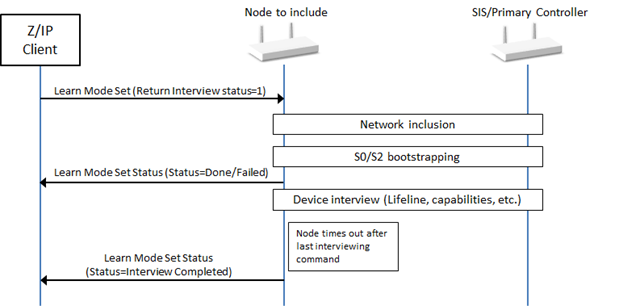
Figure 5.13 Node advertising the end of the interview process
5.2.5.10. Network management inclusion command class, version 1
The Network Management Inclusion Command Class provides functionality only available in a primary controller, inclusion controller or SIS. Since this is a dynamic property, there is a risk that a remote host tries to use commands in a controller which has become secondary in the meantime.
5.2.5.10.1. Node add command
This command is used to activate or de-activate add mode on a controller.
\requirement{CC:0034.01.01.13.001}{8}
The process of adding a node is started by the network management application sending a Node Add command to a controller. The network management application receives a status message later on indicating if the inclusion attempt was successful or not. If NWI inclusion was used, the calling application MAY re-issue this command if more nodes are to be included.
\requirement{CC:0034.01.01.12.001}{0}
The Add Mode SHOULD be disabled after a certain time to avoid adding another node unexpectedly. It is RECOMMENDED to have a timer that disables the Node Add state after a given time without any activity.
\requirement{CC:0034.01.01.11.001}{0}
Add Mode MUST be de-activated after any inclusion attempt, even if interrupted.
\requirement{CC:0034.01.01.11.008}{0}
The Node Add Status Command MUST be returned in response to this command unless it is to be ignored.
\requirement{CC:0034.01.01.11.003}{0}
This command MUST NOT be issued via multicast addressing.
\requirement{CC:0034.01.01.11.004}{0}
A receiving node MUST ignore this command if it is received via multicast addressing. The Z-Wave Multicast frame, the broadcast NodeID and the Multi Channel multi-End Point destination are all considered multicast addressing methods.
7 |
6 |
5 |
4 |
3 |
2 |
1 |
0 |
|---|---|---|---|---|---|---|---|
Command Class = COMMAND_CLASS_NETWORK_MANAGEMENT_INCLUSION (0x34) |
|||||||
Command = NODE_ADD (0x01) |
|||||||
Seq No |
|||||||
Reserved |
|||||||
Mode |
|||||||
tx Options |
|||||||
Seq No (8 bits)
Refer to Sequence number management.
Reserved
\requirement{CC:0034.01.01.11.005}{0}
This field MUST be set to 0 by a sending node and MUST be ignored by a receiving node.
This field is use to indicate to the receiving node if the Add Mode must be activated or de-activated.
\requirement{CC:0034.01.01.11.006}{0}
This field MUST comply with Table 5.64.
Value |
Identifier |
Description |
|---|---|---|
0x01 |
ADD_NODE_ANY |
Add any type of node to the network. |
0x05 |
ADD_NODE_STOP |
Stop Add Mode. The command MAY be ignored if Add Mode was not activated. The command MAY be ignored if network inclusion or security bootstrapping is ongoing. |
Examples of Add Mode activation and deactivation are given in Figure 5.14.
tx Options (1 byte)
\requirement{CC:0034.01.01.11.007}{0}
The tx Options field allows a controlling node to specify if transmissions MUST use special properties. This field MUST be treated as a bitmask and MUST comply with Table 5.65.
Value |
Option flag identifier |
Description |
|---|---|---|
0x00 |
ADD_NODE_ANY |
Transmit at normal power level without any transmit options. |
0x02 |
TRANSMIT_OPTION_LOW_POWER |
Transmit at low output power level (1/3 of normal RF range) |
0x20 |
TRANSMIT_OPTION_EXPLORE |
Allow network-wide inclusion |
\requirement{CC:0034.01.01.12.002}{0}
If the Mode is set to NODE_ADD_ANY, it is RECOMMENDED to set this field to TRANSMIT_OPTION_EXPLORE.
\requirement{CC:0034.01.01.13.002}{0}
Installer scenarios with a requirement for more confidential transfer of network security keys MAY set the flag TRANSMIT_OPTION_LOW_POWER. This requires that the new node is included in direct range of the including controller.
5.2.5.10.2. Node add status command
This command is used to report the result of the Node Add Command or report that a new node was included.
7 |
6 |
5 |
4 |
3 |
2 |
1 |
0 |
|---|---|---|---|---|---|---|---|
Command Class = COMMAND_CLASS_NETWORK_MANAGEMENT_INCLUSION (0x34) |
|||||||
Command = NODE_ADD_STATUS (0x02) |
|||||||
Seq No |
|||||||
Status |
|||||||
Reserved |
|||||||
New NodeID |
|||||||
Node Info Length |
|||||||
List. |
Z-Wave Protocol Specific Part |
||||||
Opt. Func. |
Z-Wave Protocol Specific Part |
||||||
Basic Device Class |
|||||||
Generic Device Class |
|||||||
Specific Device Class |
|||||||
Command Class 1 *) |
|||||||
… |
|||||||
Command Class N *) |
|||||||
*) Command classes may be extended –> spanning two bytes for one command class
Seq No (1 byte)
Refer to Sequence number management.
Status (1 byte)
\requirement{CC:0034.01.02.11.001}{0}
This field indicates the outcome of the add mode and MUST comply with Table 5.67.
Value |
Status identifier |
Description |
|---|---|---|
0x06 |
ADD_NODE_STATUS_DONE |
The new node has been included in the network. If the new node and controller support S0 or S2, it indicates that the network inclusion and security bootstrapping were completed successfully (This include the case where the node was granted no S2 key). |
0x07 |
ADD_NODE_STATUS_FAILED |
Transmit at low output power level (1/3 of normal RF range) |
0x09 |
ADD_NODE_STATUS_SECURITY_FAILED |
Allow network-wide inclusion |
Reserved
\requirement{CC:0034.01.02.11.002}{0}
This field MUST be set to 0 by a sending node and MUST be ignored by a receiving node.
New NodeID (1 byte)
\requirement{CC:0034.01.02.11.005}{0}
This field MUST indicate the assigned NodeID to the newly added node. This field is valid if Status is different than NODE_ADD_STATUS_FAILED.
This field MUST be set to 0x00 if no NodeID was assigned to the included node.
Node Info Length (1 byte)
\requirement{CC:0034.01.02.11.004}{4}
This field is used to indicate the length in bytes of the encapsulated Node Information fields. This field MUST be included in the length calculation. The value MUST indicate the length of the following fields:
Node Info Length (this field)
List / Z-Wave Protocol Specific Part
Opt Func / Z-Wave Protocol Specific Part
Basic Device Class
Generic Device Class
Specific Device Class
Command Class
List. (1 bit)
Refer to Node info cached report command
Opt. Func. (1 bit)
Refer to Node info cached report command
Z-Wave Protocol Specific Part
Refer to Node info cached report command
Basic Device Class (1 byte)
Refer to Node info cached report command
Generic Device Class (1 byte)
Refer to Node info cached report command
Specific Device Class (1 byte)
Refer to Node info cached report command
Command Class (N bytes)
Refer to Node info cached report command
5.2.5.10.3. Node remove command
This command is used to activate or de-activate node remove mode. The remove operation only works in direct range between the controller and the node that is to be removed.
\requirement{CC:0034.01.03.12.001}{0}
The Node Remove mode SHOULD be disabled after a certain time to avoid removing another node unexpectedly. It is RECOMMENDED to have a timer that disables the Node Remove mode after a given time without any activity.
\requirement{CC:0034.01.03.11.001}{0}
Node Remove mode MUST be de-activated after any removal attempt, even if interrupted.
\requirement{CC:0034.01.03.11.007}{0}
The Node Remove Status Command MUST be returned in response to this command unless it is ignored.
\requirement{CC:0034.01.03.11.003}{0}
This command MUST NOT be issued via multicast addressing.
\requirement{CC:0034.01.03.11.004}{0}
A receiving node MUST ignore this command if it is received via multicast addressing. The Z-Wave Multicast frame, the broadcast NodeID and the Multi Channel multi-End Point destination are all considered multicast addressing methods.
7 |
6 |
5 |
4 |
3 |
2 |
1 |
0 |
|---|---|---|---|---|---|---|---|
Command Class = COMMAND_CLASS_NETWORK_MANAGEMENT_INCLUSION (0x34) |
|||||||
Command = NODE_REMOVE (0x03) |
|||||||
Seq No |
|||||||
Reserved |
|||||||
Mode |
|||||||
Seq No (1 byte)
Refer to Sequence number management.
Reserved
\requirement{CC:0034.01.03.11.005}{0}
This field MUST be set to 0 by a sending node and MUST be ignored by a receiving node.
Mode (1 byte)
\requirement{CC:0034.01.03.11.006}{0}
This field is use to indicate to the receiving node if the node removal process must be activated or de-activated. This field MUST comply with Table 5.69.
\requirement{CC:0034.01.03.13.001}{20}
Value |
Mode identifier |
Description |
|---|---|---|
0x01 |
REMOVE_NODE_ANY |
Remove any type of node from the network |
0x05 |
REMOVE_NODE_STOP |
Stop the node removal process. The command MAY be ignored if the remove process was not activated. The command MAY be ignored if network exclusion is ongoing. |
The process of removing a node is started by sending this command with Mode set to REMOVE_NODE_ANY. The removal process is complete when a Node Remove Status command with status set to NODE_REMOVE_STATUS_DONE is returned.
5.2.5.10.4. Node remove status command
This command is used to advertise the status of a node removal attempt.
7 |
6 |
5 |
4 |
3 |
2 |
1 |
0 |
|---|---|---|---|---|---|---|---|
Command Class = COMMAND_CLASS_NETWORK_MANAGEMENT_INCLUSION (0x34) |
|||||||
Command = NODE_REMOVE_STATUS (0x04) |
|||||||
Seq No |
|||||||
Status |
|||||||
NodeID |
|||||||
Seq No (1 byte)
Refer to Sequence number management.
Status (1 byte)
\requirement{CC:0034.01.04.11.001}{0}
This field is used to advertise status of a node removal attempt. This field MUST comply with Table 5.71.
Value |
Status identifier |
Description |
|---|---|---|
0x06 |
REMOVE_NODE_STATUS_DONE |
The node has now been removed and the controller is ready to continue normal operation again. Removed NodeID is returned. |
0x07 |
REMOVE_NODE_STATUS_FAILED |
The remove process failed (no node was removed) |
NodeID (1 byte)
This field is used to advertise the NodeID that was attempted to be removed from the network.
\requirement{CC:0034.01.04.12.001}{0}
This field SHOULD be set to 0x00 if no attempt has been made.
5.2.5.10.5. Failed node remove command
This command is used to remove a non-responding node.
\requirement{CC:0034.01.07.11.001}{4}
A non-responding node is put onto the failed NodeID list by a controller when detected. In case the node responds again at a later stage, it is removed from the failed NodeID list. A node MUST be on the failed NodeID list and as an extra precaution also fail to respond before it is removed. Responding nodes MUST NOT be removed.
\requirement{CC:0034.01.07.11.002}{0}
The Failed Node Remove Status Command MUST be returned in response to this command when the removal attempt has been made.
\requirement{CC:0034.01.07.11.003}{0}
This command MUST NOT be issued via multicast addressing.
\requirement{CC:0034.01.07.11.004}{0}
A receiving node MUST ignore this command if it is received via multicast addressing. The Z-Wave Multicast frame, the broadcast NodeID and the Multi Channel multi-End Point destination are all considered multicast addressing methods.
7 |
6 |
5 |
4 |
3 |
2 |
1 |
0 |
|---|---|---|---|---|---|---|---|
Command Class = COMMAND_CLASS_NETWORK_MANAGEMENT_INCLUSION (0x34) |
|||||||
Command = FAILED_NODE_REMOVE (0x07) |
|||||||
Seq No |
|||||||
NodeID |
|||||||
Seq No (1 byte)
Refer to Sequence number management.
NodeID (1 byte)
\requirement{CC:0034.01.07.11.005}{0}
This field is used to specify the NodeID of the failing node which MUST be removed.
5.2.5.10.6. Node neighbor update request command
This command is used to instruct a node with NodeID to perform a Node Neighbor Update operation in order to update the topology on the controller.
\requirement{CC:0034.01.0B.11.001}{0}
The Node Neighbor Update Status Command MUST be returned in response to this command when the neighbor search is completed.
\requirement{CC:0034.01.0B.11.002}{0}
This command MUST NOT be issued via multicast addressing.
\requirement{CC:0034.01.0B.11.003}{0}
A receiving node MUST ignore this command if it is received via multicast addressing. The Z-Wave Multicast frame, the broadcast NodeID and the Multi Channel multi-End Point destination are all considered multicast addressing methods.
7 |
6 |
5 |
4 |
3 |
2 |
1 |
0 |
|---|---|---|---|---|---|---|---|
Command Class = COMMAND_CLASS_NETWORK_MANAGEMENT_INCLUSION (0x34) |
|||||||
Command = NODE_NEIGHBOR_UPDATE_REQUEST (0x0B) |
|||||||
Seq No |
|||||||
NodeID |
|||||||
Seq No (1 byte)
Refer to Sequence number management.
NodeID (1 byte)
\requirement{CC:0034.01.0B.11.004}{0}
This field is used to specify the NodeID of the failing node which MUST perform the Node Neighbor Update operation.
5.2.5.10.7. Node neighbor update status command
This command is used to report the status of a Node Neighbor Update operation.
7 |
6 |
5 |
4 |
3 |
2 |
1 |
0 |
|---|---|---|---|---|---|---|---|
Command Class = COMMAND_CLASS_NETWORK_MANAGEMENT_INCLUSION (0x34) |
|||||||
Command = NODE_NEIGHBOR_UPDATE_STATUS (0x0C) |
|||||||
Seq No |
|||||||
Status |
|||||||
Seq No (1 byte)
Refer to Sequence number management.
Status (1 byte)
\requirement{CC:0034.01.0C.11.001}{0}
This field is used to advertise status of the neighbor update operation. This field MUST comply with Table 5.75.
Value |
Status identifier |
Description |
|---|---|---|
0x22 |
NEIGHBOR_UPDATE_STATUS_DONE |
New neighbor list received |
0x23 |
NEIGHBOR_UPDATE_STATUS_FAIL |
Getting new neighbor list failed |
5.2.5.10.8. Return route assign command
This command is used to make a controller assign static return routes (up to 4) to an end node node. This allows the end nodes to communicate directly with other nodes.
Up to 5 different destinations can be allocated return routes. Attempts to assign new return routes when all 5 destinations already are allocated will be ignored.
Allocated return routes can only be cleared using the Return Route Delete Command.
The controller calculates the shortest routes from the end node (Source NodeID field) to the destination node (Destination NodeID field) and transmits the return routes to the end node (Source NodeID field).
\requirement{CC:0034.01.0D.11.001}{0}
The Return Route Assign Complete Command MUST be returned in response to this command when the route assignment is completed.
\requirement{CC:0034.01.0D.11.002}{0}
This command MUST NOT be issued via multicast addressing.
\requirement{CC:0034.01.0D.11.003}{0}
A receiving node MUST ignore this command if it is received via multicast addressing. The Z-Wave Multicast frame, the broadcast NodeID and the Multi Channel multi-End Point destination are all considered multicast addressing methods.
7 |
6 |
5 |
4 |
3 |
2 |
1 |
0 |
|---|---|---|---|---|---|---|---|
Command Class = COMMAND_CLASS_NETWORK_MANAGEMENT_INCLUSION (0x34) |
|||||||
Command = RETURN_ROUTE_ASSIGN (0x0D) |
|||||||
Seq No |
|||||||
Source NodeID |
|||||||
Destination NodeID |
|||||||
Seq No (1 byte)
Refer to Sequence number management.
Source NodeID (1 byte)
This field is used to specify the NodeID of the node which will be assigned the return route.
Destination NodeID (1 byte)
This field is used to specify the destination NodeID for which the Source NodeID will have a route assigned.
5.2.5.10.9. Return route assign complete command
This command is used to indicate the status of a return route assignment attempt.
7 |
6 |
5 |
4 |
3 |
2 |
1 |
0 |
|---|---|---|---|---|---|---|---|
Command Class = COMMAND_CLASS_NETWORK_MANAGEMENT_INCLUSION (0x34) |
|||||||
Command = RETURN_ROUTE_ASSIGN_COMPLETE (0x0E) |
|||||||
Seq No |
|||||||
Status |
|||||||
Seq No (1 byte)
Refer to Sequence number management.
Status (1 byte)
\requirement{CC:0034.01.0E.11.001}{0}
This field is used to advertise status of the return route assignment attempt. This field MUST comply with Table 5.78.
Value |
Option identifier |
Description |
|---|---|---|
0x00 |
TRANSMIT_COMPLETE_OK |
Successfully transmitted |
0x01 |
TRANSMIT_COMPLETE_NO_ACK |
No acknowledgement is received before timeout from the destination node. Acknowledgement is discarded in case it is received after the time out. |
0x02 |
TRANSMIT_COMPLETE_FAIL |
Not possible to transmit data because the Z-Wave network is busy (jammed). |
0x03 |
N/A |
Reserved |
0x04 |
TRANSMIT_COMPLETE_NOROUTE |
No route found to assign to the destination. No frame was transmitted. |
0x05 |
TRANSMIT_COMPLETE_VERIFIED |
This status code is identical to 0x00. The route was successfully transmitted. |
5.2.5.10.10. Return route delete command
This command is used to make a controller delete all static return routes from an end node. Allocated return routes can only be removed using this command. All return routes are cleared when using this command.
\requirement{CC:0034.01.0F.12.001}{0}
After issuing this command, an application SHOULD issue Return Route Assign Commands to create return routes for all relevant associations.
\requirement{CC:0034.01.0F.11.001}{0}
The Return Route Delete Complete Command MUST be returned in response to this command.
\requirement{CC:0034.01.0F.11.002}{0}
This command MUST NOT be issued via multicast addressing.
\requirement{CC:0034.01.0F.11.003}{0}
A receiving node MUST ignore this command if it is received via multicast addressing. The Z-Wave Multicast frame, the broadcast NodeID and the Multi Channel multi-End Point destination are all considered multicast addressing methods.
7 |
6 |
5 |
4 |
3 |
2 |
1 |
0 |
|---|---|---|---|---|---|---|---|
Command Class = COMMAND_CLASS_NETWORK_MANAGEMENT_INCLUSION (0x34) |
|||||||
Command = RETURN_ROUTE_DELETE (0x0F) |
|||||||
Seq No |
|||||||
NodeID |
|||||||
Seq No (1 byte)
Refer to Sequence number management.
NodeID (1 byte)
\requirement{CC:0034.01.0F.11.004}{0}
This field is used to specify the NodeID of which the return routes MUST be deleted.
5.2.5.10.11. Return route delete complete command
This command is used to indicate the status of a return route deletion attempt.
7 |
6 |
5 |
4 |
3 |
2 |
1 |
0 |
|---|---|---|---|---|---|---|---|
Command Class = COMMAND_CLASS_NETWORK_MANAGEMENT_INCLUSION (0x34) |
|||||||
Command = RETURN_ROUTE_DELETE_COMPLETE (0x10) |
|||||||
Seq No |
|||||||
Status |
|||||||
Seq No (1 byte)
Refer to Sequence number management.
Status (1 byte)
\requirement{CC:0034.01.10.11.001}{0}
This field is used to advertise status of the return route deletion attempt. This field MUST comply with Table 5.81.
Value |
Option identifier |
Description |
|---|---|---|
0x00 |
TRANSMIT_COMPLETE_OK |
Successfully transmitted |
0x01 |
TRANSMIT_COMPLETE_NO_ACK |
No acknowledgement is received before timeout from the destination node. Acknowledgement is discarded in case it is received after the time out. |
0x02 |
TRANSMIT_COMPLETE_FAIL |
Not possible to transmit data because the Z-Wave network is busy (jammed). |
5.2.5.10.12. Use cases and frame flows
5.2.5.10.12.1. Z/IP Client requesting a node to interrupt Add Mode
The frame flow for interrupting Add Mode is shown in Figure 5.14.
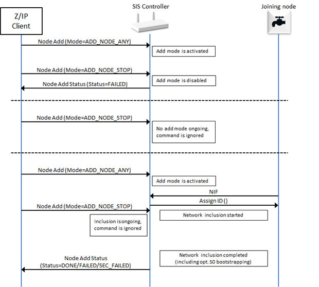
Figure 5.14 Z/IP Client requesting a node to interrupt Add Mode
5.2.5.11. Network management inclusion command class, version 2
5.2.5.11.1. Compatibility considerations
\requirement{CC:0034.02.00.21.001}{8}
The Network Management Inclusion Command Class, version 2 is backwards compatible with Network Management Inclusion Command Class, version 1. A node supporting Network Management Inclusion Command Class, version 2 MUST also support Network Management Inclusion Command Class, version 1.
All commands not mentioned in this version remain unchanged from version 1.
The following commands are introduced to support the multiple security keys and DSK functionalities of the Security 2 Command Class:
Node Add Keys Report Command
Node Add Keys Set Command
Node Add DSK Report Command
Node Add DSK Set Command
The following command has been extended to support the new S2/inclusion controller bootstrapping process:
Node Add Command
Node Add Status Command
Failed Node Replace Command
Failed Node Replace Status Command
Use-cases and frames flows for the new functionalities of this Command Class are shown in Use cases and frame flows.
5.2.5.11.2. Node add command
This command is used to add nodes to the Z-Wave network.
\requirement{CC:0034.02.01.11.005}{0}
The Node Add Status Command MUST be returned in response to this command unless it is to be ignored.
\requirement{CC:0034.02.01.11.002}{0}
This command MUST NOT be issued via multicast addressing.
\requirement{CC:0034.02.01.11.003}{0}
A receiving node MUST NOT return a response if this command is received via multicast addressing. The Z-Wave Multicast frame, the broadcast NodeID and the Multi Channel multi-End Point destination are all considered multicast addressing methods.
7 |
6 |
5 |
4 |
3 |
2 |
1 |
0 |
|---|---|---|---|---|---|---|---|
Command Class = COMMAND_CLASS_NETWORK_MANAGEMENT_INCLUSION (0x34) |
|||||||
Command = NODE_ADD (0x01) |
|||||||
Seq No |
|||||||
Reserved |
|||||||
Mode |
|||||||
tx Options |
|||||||
Fields not described in this version remain unchanged from version 1.
Mode (1 byte)
\requirement{CC:0034.02.01.11.004}{4}
This field is use to indicate to the receiving node which mode to use for the inclusion of a new node. This field MUST comply with Table 5.83.
\requirement{CC:0034.02.01.13.001}{20}
Value |
Identifier |
Description |
Version |
|---|---|---|---|
0x01 |
NODE_ADD_ANY |
Add any type of node to the network and allow Security 0 bootstrapping |
1 |
0x05 |
NODE_ADD_STOP |
Stop Add Mode. The command MAY be ignored if Add Mode was not activated. The command MAY be ignored if network inclusion or security bootstrapping is ongoing |
1 |
0x07 |
NODE_ADD_ANY_S2 |
Not possible to transmit data because the Z-Wave network is busy (jammed). |
2 |
Examples of Add Mode activation and deactivation are also given in Z/IP Client requesting a node to interrupt Add Mode.
5.2.5.11.3. Node add status command
This command is used to report the result of a node inclusion.
7 |
6 |
5 |
4 |
3 |
2 |
1 |
0 |
|---|---|---|---|---|---|---|---|
Command Class = COMMAND_CLASS_NETWORK_MANAGEMENT_INCLUSION (0x34) |
|||||||
Command = NODE_ADD_STATUS (0x02) |
|||||||
Seq No |
|||||||
Status |
|||||||
Reserved |
|||||||
New NodeID |
|||||||
Node Info Length |
|||||||
List. |
Z-Wave Protocol Specific Part |
||||||
Opt. Func. |
Z-Wave Protocol Specific Part |
||||||
Basic Device Class |
|||||||
Generic Device Class |
|||||||
Specific Device Class |
|||||||
Command Class 1 *) |
|||||||
… |
|||||||
Command Class N *) |
|||||||
Granted Keys |
|||||||
KEX Fail Type |
|||||||
*) Command classes may be extended –> spanning two bytes for one command class
Fields not described in this version remain unchanged from version 1.
Command Class (N bytes)
Refer to Node info cached report command and Table 5.27.
\requirement{CC:0034.02.02.11.001}{0}
The Security Command Class Mark (0xF100) MUST indicate command classes supported using the highest listed Security Key in the Granted Key field value.
Granted Keys (8 bits)
This field is used to indicate which network keys were granted during bootstrapping.
\requirement{CC:0034.02.02.11.002}{0}
This field MUST be treated as a bitmask and comply with Table 5.85
Bit |
Description |
|---|---|
0 |
Indicates the Unauthenticated Security Class Key |
1 |
Indicates the Authenticated Security Class Key |
2 |
Indicates the Access Control Security Class Key |
7 |
Indicates the Security 0 Network Key |
KEX Fail Type (8 bits)
This field is used to indicate which error occurred in case S2 bootstrapping was not successful.
\requirement{CC:0034.02.02.11.003}{4}
This field MUST comply with Table 5.86.
Value |
KEX Fail Type Identifier |
Description |
|---|---|---|
0x00 |
Bootstrapping was successful |
|
0x01 |
KEX_FAIL_KEX_KEY |
Key failure indicating that no match exists between requested/granted keys in the network. |
0x02 |
KEX_FAIL_KEX_SCHEME |
Scheme failure indicating that no scheme is supported by controller or joining node specified an invalid scheme. |
0x03 |
KEX_FAIL_KEX_CURVES |
Curve failure indicating that no curve is supported by controller or joining node specified an invalid curve. |
0x05 |
KEX_FAIL_DECRYPT |
Node failed to decrypt received frame. |
0x06 |
KEX_FAIL_CANCEL |
User has cancelled the S2 bootstrapping. |
0x07 |
KEX_FAIL_AUTH |
The Echo KEX Set/Report frame did not match the earlier exchanged frame. |
0x08 |
KEX_FAIL_KEY_GET |
The joining node has requested a key, which was not granted by the including node at an earlier stage. |
0x09 |
KEX_FAIL_KEY_VERIFY |
Including node failed to decrypt and hence verify the received frame encrypted with exchanged key. |
0x0A |
KEX_FAIL_KEY_REPORT |
The including node has transmitted a frame containing a different key than what is currently being exchanged. |
5.2.5.11.4. Node add keys report command
This command is used to inform which S2 keys have been requested during S2 bootstrapping.
\requirement{CC:0034.02.11.11.001}{0}
The Node Add Keys Set Command MUST be returned in response to this command.
\requirement{CC:0034.02.11.11.002}{0}
This command MUST NOT be issued via multicast addressing.
\requirement{CC:0034.02.11.11.003}{0}
A receiving node MUST NOT return a response if this command is received via multicast addressing. The Z-Wave Multicast frame, the broadcast NodeID and the Multi Channel multi-End Point destination are all considered multicast addressing methods.
7 |
6 |
5 |
4 |
3 |
2 |
1 |
0 |
|---|---|---|---|---|---|---|---|
Command Class = COMMAND_CLASS_NETWORK_MANAGEMENT_INCLUSION (0x34) |
|||||||
Command = NODE_ADD_KEYS_REPORT (0x11) |
|||||||
Seq No |
|||||||
Reserved |
Request CSA |
||||||
Requested Keys |
|||||||
Seq No (1 byte)
Refer to Sequence number management.
Request CSA (1 bit)
This field is used to indicate if the joining node is requesting CSA (Client-Side Authentication, refer to Section 4).
\requirement{CC:0034.02.11.11.004}{0}
The value 1 MUST indicate that the node requests CSA.
The value 0 MUST indicate that the node does not request CSA.
Requested Keys (1 bytes)
This field is used to advertise the requested keys by the joining node.
\requirement{CC:0034.02.11.11.005}{0}
This field MUST be treated as a bitmask and comply with Table 5.85
\requirement{CC:0034.02.12.11.004}{0}
This field MUST be set to 0x00 if the Accept field is set to 0.
Accept (1 bit)
This field is used to indicate if the S2 bootstrapping process is accepted by the user and must continue.
\requirement{CC:0034.02.12.11.005}{0}
The value 0 MUST indicate that the S2 bootstrapping is not accepted and MUST be interrupted. The value 1 MUST indicate that the S2 bootstrapping is accepted and MUST continue.
5.2.5.11.5. Node add DSK report command
This command is used to report the DSK of the node being S2 bootstrapped and indicates whether an input is needed for node authentication.
\requirement{CC:0034.02.13.11.001}{0}
The Node Add DSK Set Command MUST be returned in response to this command.
\requirement{CC:0034.02.13.11.002}{0}
This command MUST NOT be issued via multicast addressing.
\requirement{CC:0034.02.13.11.003}{0}
A receiving node MUST NOT return a response if this command is received via multicast addressing. The Z-Wave Multicast frame, the broadcast NodeID and the Multi Channel multi-End Point destination are all considered multicast addressing methods.
7 |
6 |
5 |
4 |
3 |
2 |
1 |
0 |
|---|---|---|---|---|---|---|---|
Command Class = COMMAND_CLASS_NETWORK_MANAGEMENT_INCLUSION (0x34) |
|||||||
Command = NODE_ADD_DSK_REPORT (0x13) |
|||||||
Seq No |
|||||||
Reserved |
Input DSK Length |
||||||
DSK 1 |
|||||||
… |
|||||||
DSK 16 |
|||||||
Seq No (8 bits)
Refer to Sequence number management.
Input DSK Length (4 bits)
\requirement{CC:0034.02.13.11.004}{0}
This field is used to indicate how many DSK bytes MUST be input as a minimum to authenticate the node being included.
\requirement{CC:0034.02.13.11.005}{0}
The value 0 MUST indicate that no user input is necessary (e.g. Unauthenticated Security Class or CSA has been granted).
DSK (16 bytes)
This field is used to transmit the DSK of the node being S2 bootstrapped. Refer to Section 4.
5.2.5.11.6. Node add DSK set command
This command is used to indicate the S2 bootstrapping controller if the DSK is accepted and report the user input when needed.
7 |
6 |
5 |
4 |
3 |
2 |
1 |
0 |
|---|---|---|---|---|---|---|---|
Command Class = COMMAND_CLASS_NETWORK_MANAGEMENT_INCLUSION (0x34) |
|||||||
Command = NODE_ADD_DSK_SET (0x14) |
|||||||
Seq No |
|||||||
Accept |
Reserved |
Input DSK Length |
|||||
DSK 1 |
|||||||
… |
|||||||
DSK N |
|||||||
Seq No (1 byte)
Refer to Sequence number management.
Input DSK Length (4 bits)
This field indicates the length in bytes of the DSK input by the user.
\requirement{CC:0034.02.14.11.001}{0}
This field MUST be set to the same or a higher value than the ”Input DSK Length” field value received in the Node Add DSK Report Command that caused this command to be returned.
\requirement{CC:0034.02.14.11.002}{0}
The value 0 MUST indicate that no user input has been done (e.g. Unauthenticated Security Class, CSA has been granted or user refused to input DSK).
Input DSK (N bytes)
\requirement{CC:0034.02.14.11.003}{0}
This field indicates the DSK input by the user. A receiving node (Z/IP gateway) MUST overwrite the part of the DSK with the Input DSK contained in this frame
\requirement{CC:0034.02.14.11.004}{0}
The length of this field in bytes MUST be according to the Input DSK Length field value. If the Input DSK Length is set to 0, this field MUST be omitted.
Accept (1 bit)
This field is used to indicate if the DSK Report is accepted by the user and if S2 bootstrapping must continue.
\requirement{CC:0034.02.14.11.005}{0}
The value 0 MUST indicate that the DSK Report is not accepted and S2 bootstrapping MUST be interrupted.
The value 1 MUST indicate that the DSK Report is accepted and S2 bootstrapping MUST continue.
5.2.5.11.7. Failed node replace command
This command is used to replace a non-responding node with a new one in having the same NodeID.
\requirement{CC:0034.02.09.11.005}{0}
The Failed Node Replace Status Command MUST be returned in response to this command unless it is to be ignored.
\requirement{CC:0034.02.09.11.002}{0}
This command MUST NOT be issued via multicast addressing.
\requirement{CC:0034.02.09.11.003}{0}
A receiving node MUST ignore this command if it is received via multicast addressing. The Z-Wave Multicast frame, the broadcast NodeID and the Multi Channel multi-End Point destination are all considered multicast addressing methods.
7 |
6 |
5 |
4 |
3 |
2 |
1 |
0 |
|---|---|---|---|---|---|---|---|
Command Class = COMMAND_CLASS_NETWORK_MANAGEMENT_INCLUSION (0x34) |
|||||||
Command = FAILED_NODE_REPLACE (0x09) |
|||||||
Seq No |
|||||||
NodeID |
|||||||
tx Options |
|||||||
… |
|||||||
Mode |
|||||||
Fields not described in this version remain unchanged from version 1.
Mode (1 byte)
This field indicates the type of operation for the failed replace process.
\requirement{CC:0034.02.09.11.004}{0}
This field MUST comply with Table 5.91
\requirement{CC:0034.02.09.13.001}{20}
Value |
Identifier |
Description |
Version |
|---|---|---|---|
0x01 |
START_FAILED_NODE_REPLACE |
Initiate a failed node replace process. |
1 |
0x05 |
STOP_FAILED_NODE_REPLACE |
Cancel a failed node replace process. The command MAY be ignored if no replaced failed process is active. The command MAY be ignored if network inclusion is ongoing |
1 |
0x07 |
START_FAILED_NODE_REPLACE_S2 |
Initiate a failed node replace process and allow S2 bootstrapping for the new node |
2 |
5.2.5.11.8. Failed node replace status command
This command is used to indicate the progress of the Replace Failed Node Command.
7 |
6 |
5 |
4 |
3 |
2 |
1 |
0 |
|---|---|---|---|---|---|---|---|
Command Class = COMMAND_CLASS_NETWORK_MANAGEMENT_INCLUSION (0x34) |
|||||||
Command = FAILED_NODE_REPLACE_STATUS (0x0A) |
|||||||
Seq No |
|||||||
Status |
|||||||
Node ID |
|||||||
Granted Keys |
|||||||
KEX Fail Type |
|||||||
Fields not described in this version remain unchanged from version 1.
Granted Keys (8 bits)
This field is used to indicate which network keys were granted during bootstrapping.
\requirement{CC:0034.02.0A.11.001}{0}
This field MUST be treated as a bitmask and comply with Table 5.85
KEX Fail Type (8 bits )
Refer to Node add status command and Table 5.86
5.2.5.11.9. Use cases and frame flows
5.2.5.11.9.1. Z/IP Client with SIS or Primary controller including an S2 node
The frame flow for an S2 capable node inclusion using the Network Management Inclusion Command Class is shown in Figure 5.15.
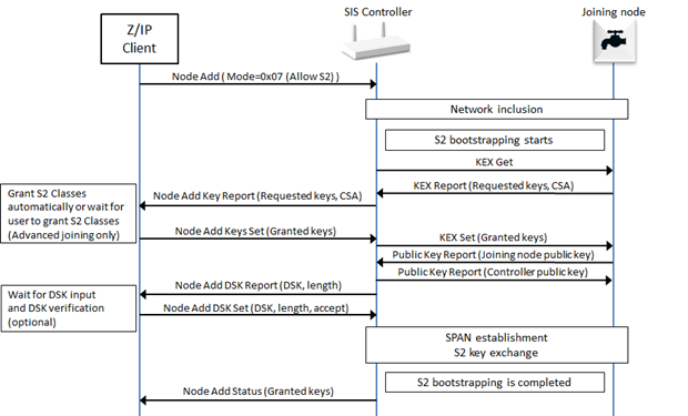
Figure 5.15 Node inclusion with a SIS/Primary controller
5.2.5.11.9.2. Z/IP Client with an S2 inclusion controller including an S2 node
When performing S2 bootstrapping, the unsolicited destination of the Z/IP Gateway will receive a unsolicited Node Add S2 Keys Report from the Z/IP Gateway. The Z/IP Client at this point has two options:
\requirement{CC:0034.02.00.11.001}{0}
Automatically grant requested S2 Classes without presenting a user dialog in the S2 Keys Report step. In this case, the Z/IP Client MUST present a user dialog in next step before sending the DSK Set
\requirement{CC:0034.02.00.11.002}{0} \requirement{CC:0034.02.00.13.001}{4}
Using advanced joining where the user MUST confirm the specific keys being requested in a dialog, before continuing to next step. In this case, the Z/IP MAY present a user dialog in next step before sending the DSK Set, if required by the S2 Classes being granted.
This is done without the SIS having entered Add Node mode. From this point on the S2 inclusion frame flow is same as when including through the SIS.
The frame flow for the node inclusion when an S2 capable inclusion controller has been used for including a new S2 capable node is shown in Figure 5.16.
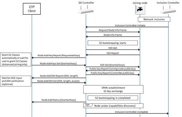
Figure 5.16 Node inclusion with an S2 inclusion controller
5.2.5.11.9.3. Z/IP client with an S2 inclusion controller including an S0 node
\requirement{CC:0034.02.00.13.002}{4}
The unsolicited destination of the Z/IP Gateway will receive an unsolicited Node Add Status Report from the Z/IP Gateway. The unsolicited destination Z/IP Client MAY show a dialog informing that a node was included by an inclusion controller.
The frame flow for an S0 capable node inclusion using an S2 capable inclusion controller including is shown in Figure 5.17.
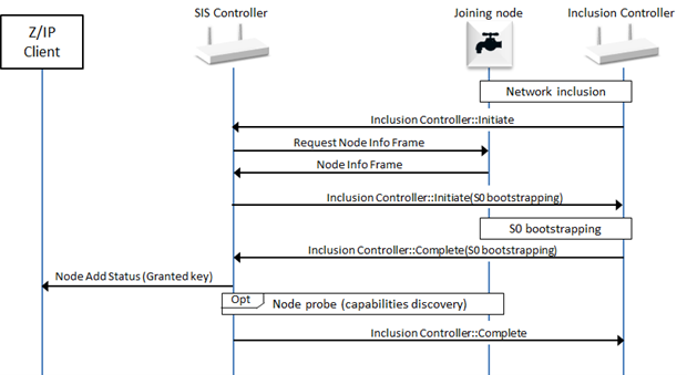
Figure 5.17 S0 node inclusion with an S2 inclusion controller
5.2.5.12. Network management inclusion command class, version 3
5.2.5.12.1. Compatibility considerations
The Network Management Inclusion Command Class, version 3 is backwards compatible with the Network Management Inclusion Command Class, version 2.
\requirement{CC:0034.03.00.21.001}{0}
A node supporting the Network Management Inclusion Command Class, version 2 MUST also support the Network Management Inclusion Command Class, version 2.
\requirement{CC:0034.03.00.21.002}{0}
All commands and fields not mentioned in this version MUST remain unchanged from version 2.
The following command has been extended to support the report of a Smart Start node:
Node Add Status Command
The following commands are introduced in order to support the Smart Start functionality:
Included Node Information Frame Report Command
Smart Start Join Started Command
\requirement{CC:0034.03.00.21.003}{0}
Frame flows for the new functionalities of this Command Class are shown in “ref”network_protocol_command_classes-command_class_definitions-network_management_command_classes-network_management_inclusion_command_class_version_3-use_cases_and_frame_flows. A Z/IP Gateway MUST comply with Network management inclusion command class, version 3.
\requirement{CC:0034.03.00.21.004}{0}
A supporting node MUST issue the Node Add Status Command, Included Node Information Frame Report Command and the Smart Start Join Started Command to the first and the second unsolicited destinations.
5.2.5.12.1.1. Command class dependencies
\requirement{CC:0034.03.00.21.005}{0}
A node supporting the Network Management Inclusion Command Class, version 3 MUST also support the Node Provisioning Command Class, version 1.
5.2.5.12.2. Node add status command
This command is used to report the result of the Node Add Command or report that a new node was included.
7 |
6 |
5 |
4 |
3 |
2 |
1 |
0 |
|---|---|---|---|---|---|---|---|
Command Class = COMMAND_CLASS_NETWORK_MANAGEMENT_INCLUSION (0x34) |
|||||||
Command = NODE_ADD_STATUS (0x02) |
|||||||
Seq No |
|||||||
Status |
|||||||
Reserved |
|||||||
New NodeID |
|||||||
Node Info Length |
|||||||
List. |
Z-Wave Protocol Specific Part |
||||||
Opt. Func. |
Z-Wave Protocol Specific Part |
||||||
Basic Device Class |
|||||||
Generic Device Class |
|||||||
Specific Device Class |
|||||||
Command Class 1 *) |
|||||||
… |
|||||||
Command Class N *) |
|||||||
Granted Keys |
|||||||
KEX Fail Type |
|||||||
Reserved |
DSK Length |
||||||
DSK 1 |
|||||||
… |
|||||||
DSK L |
|||||||
\requirement{CC:0034.03.02.11.001}{0}
Fields not described below MUST remain unchanged from version 2.
Status (8 bits)
\requirement{CC:0034.03.02.11.002}{0}
This field indicates the outcome of the add mode and MUST comply with Table 5.94.
Value |
Status identifier |
Description |
Version |
|---|---|---|---|
0x06 |
ADD_NODE_STATUS_DONE |
The new node has been included in the network. If the new node and controller support S0 or S2, it indicates that the network inclusion and security bootstrapping were completed successfully. (This includes the case where the node was granted no S2 key) |
1 |
0x07 |
ADD_NODE_STATUS_FAILED |
The process failed, no new node was added in the network. Version 3: This status is also used if the node failed a smart start inclusion and has been removed. In this case, it may attempt the inclusion again. |
1 |
0x09 |
ADD_NODE_STATUS_SECURITY_FAILED |
Node has been included but the security bootstrapping failed |
1 |
DSK Length (5 bits)
\requirement{CC:0034.03.02.11.003}{0}
This field MUST indicate the length of the DSK field in bytes.
\requirement{CC:0034.03.02.11.004}{0}
This field MUST be set to 0 if the added node does not support the S2 Command Class.
\requirement{CC:0034.03.02.11.005}{0}
This field MUST be set to 16 if the added node supports the S2 Command Class.
DSK (L bytes)
\requirement{CC:0034.03.02.11.006}{0}
This field MUST advertise the DSK of the node that has been added to the network.
\requirement{CC:0034.03.02.11.007}{0}
The length of this field (in bytes) MUST be according to the DSK Length field value. This field MUST be omitted if the DSK Length field is set to 0.
5.2.5.12.3. Included node information frame report command
\requirement{CC:0034.03.19.11.006}{0}
This command MUST be sent to the (first and second) unsolicited destinations when an Included NIF (INIF) is received and the following conditions are fulfilled:
The advertised NHID matches an entry in the provisioning list
The advertised HomeID is different than the current network HomeID.
\requirement{CC:0034.03.19.11.007}{0}
A node issuing this command MUST subsequently issue a Node Provisioning Report Command for the matched entry in the provisioning list.
With the two commands, a Z/IP client can use the relevant information to guide the user on how to perform a reset operation on the device.
7 |
6 |
5 |
4 |
3 |
2 |
1 |
0 |
|---|---|---|---|---|---|---|---|
Command Class = COMMAND_CLASS_NETWORK_MANAGEMENT_INCLUSION (0x34) |
|||||||
Command = INCLUDED_NIF_REPORT (0x19) |
|||||||
Seq No |
|||||||
Reserved |
DSK Length |
||||||
DSK 1 |
|||||||
… |
|||||||
DSK N |
|||||||
Seq No (1 byte)
Refer to Sequence number management.
Reserved
\requirement{CC:0034.03.19.11.002}{0}
This field MUST be set to 0 by a sending node and MUST be ignored by a receiving node.
DSK Length (5 bits)
\requirement{CC:0034.03.19.11.008}{0}
This field MUST indicate the length of the DSK field in bytes.
\requirement{CC:0034.03.19.11.009}{0}
This field MUST be set to 16.
DSK (N bytes)
\requirement{CC:0034.03.19.11.00A}{0}
This field MUST advertise the DSK of the provisioning list entry that has been matched from the NHID in the received INIF.
\requirement{CC:0034.03.19.11.00B}{0}
The length of this field (in bytes) MUST be according to the DSK Length field value.
5.2.5.12.4. Smart start join started command
\requirement{CC:0034.03.15.11.001}{0}
This command MUST be sent to the (first and second) unsolicited destinations when a Smart Start inclusion starts.
\requirement{CC:0034.03.15.11.002}{0}
The Add Node Status Command MUST be issued after the Smart Start inclusion and S2 bootstrapping attempts took place.
7 |
6 |
5 |
4 |
3 |
2 |
1 |
0 |
|---|---|---|---|---|---|---|---|
Command Class = COMMAND_CLASS_NETWORK_MANAGEMENT_INCLUSION (0x34) |
|||||||
Command = SMART_START_JOIN_STARTED_REPORT (0x15) |
|||||||
Seq No |
|||||||
Reserved |
DSK Length |
||||||
DSK 1 |
|||||||
… |
|||||||
DSK N |
|||||||
Seq No (1 byte)
Refer to Sequence number management.
DSK Length (5 bits)
\requirement{CC:0034.03.15.11.003}{0}
This field MUST indicate the length of the DSK field in bytes.
\requirement{CC:0034.03.15.11.004}{0}
This field MUST be set to 16.
DSK (N bytes)
This field is used to advertise the DSK for the Provisioning List entry which starts the Smart Start inclusion process.
\requirement{CC:0034.03.15.11.005}{0}
The length of this field (in bytes) MUST be according to the DSK Length field value.
5.2.5.12.5. Usage and frame flows
5.2.5.12.5.1. Z/IP Gateway adding a smart start node that is on the provisioning list
The frame flow for a Smart Start inclusion of a node previously added on the provisioning list is shown in Figure 5.18.
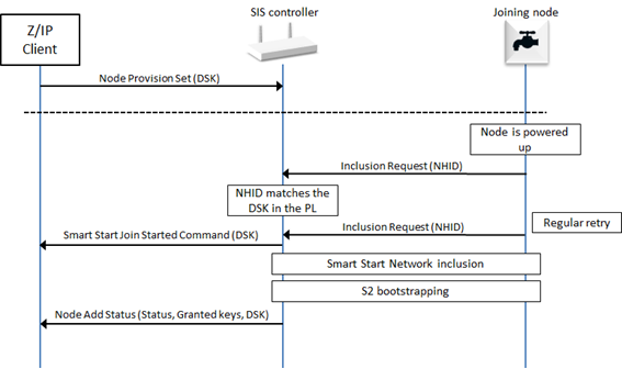
Figure 5.18 Smart Start inclusion
5.2.5.12.5.2. Z/IP Gateway adding a smart start node that is subsequently added on the provisioning list
The frame flow for a Smart Start inclusion of a node subsequently added on the provisioning list is shown in Figure 5.19.
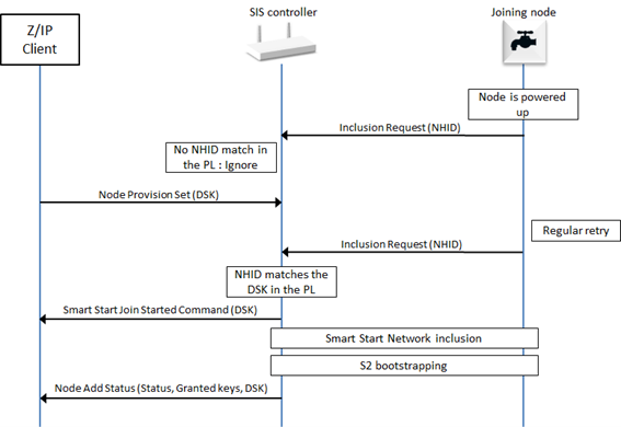
Figure 5.19 Smart Start inclusion (2)
5.2.5.12.5.3. Z/IP Gateway receiving an INIF from a node (the provisioning list) included in another network
The frame flow for a Smart Start inclusion of a node included in another network is shown in Figure 5.20.
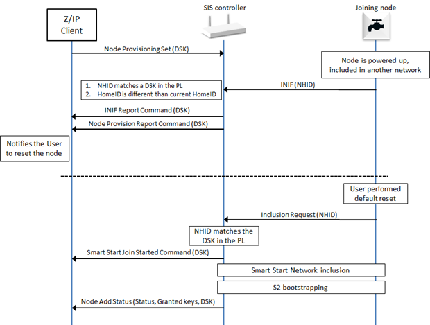
Figure 5.20 Smart Start inclusion (3)
5.2.5.12.5.4. Z/IP Gateway including an S2 only node that is on the provisioning list
The frame flow for an S2 only node (non-Smart Start) inclusion is shown in Figure 5.21. The Z/IP Client can decide to automatically grant the requested S2 keys or ask the user for confirmation.
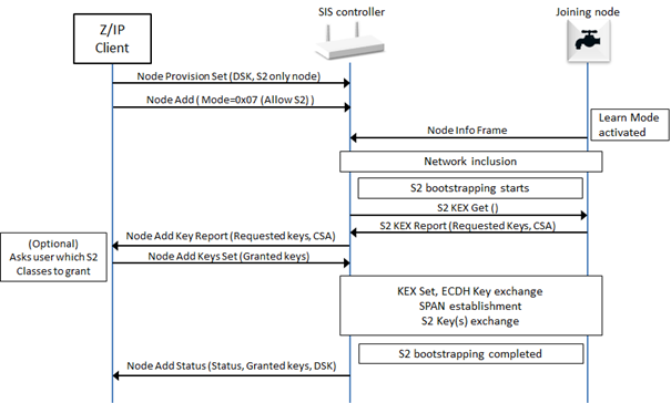
Figure 5.21 S2 Only Node inclusion with user interaction
5.2.5.13. Network management inclusion command class, version 4
5.2.5.13.1. Compatibility considerations
The Network Management Inclusion Command Class, version 4 is backwards compatible with the Network Management Inclusion Command Class, version 3.
A node supporting the Network Management Inclusion Command Class, version 4 MUST also support the Network Management Inclusion Command Class, version 3.
All commands and fields not mentioned in this version MUST remain unchanged from version 3.
This version of the Network Management Inclusion Command Class introduces support for the Z-Wave Long Range protocol. The following commands are updated:
Node Remove Status Command
Failed Node Remove Command
Failed Node Remove Status Command
The following command is added:
Extended Node Add Status Command
5.2.5.13.1.1. Command class dependencies
A node supporting the Network Management Inclusion Command Class, version 4 MUST also support the Node Provisioning Command Class, version 1.
A node supporting the Network Management Inclusion Command Class, version 4 MUST also support the Node Provisioning Bootstrapping Mode TLV (type=0x36) with value set to 0x02 (Z-Wave Long Range SmartStart Bootstrapping)
Node remove status command
This command is used to advertise the status of a node removal attempt.
7 |
6 |
5 |
4 |
3 |
2 |
1 |
0 |
|---|---|---|---|---|---|---|---|
Command Class = COMMAND_CLASS_NETWORK_MANAGEMENT_INCLUSION (0x34) |
|||||||
Command = NODE_REMOVE_STATUS (0x04) |
|||||||
Seq No |
|||||||
Status |
|||||||
NodeID |
|||||||
Extended NodeID (MSB) |
|||||||
Extended NodeID (LSB) |
|||||||
Fields not described below MUST remain unchanged from version 3.
NodeID (1 byte)
This field is used to advertise the NodeID that was attempted to be removed from the network.
This field SHOULD be set to 0x00 if no attempt has been made.
This field MUST be set to 0xFF if the removed NodeID is greater than 255.
Extended NodeID (2 bytes)
This field is used to advertise the NodeID that was attempted to be removed from the network.
This field MUST be set to the actual NodeID that was attempted to be removed from the network.
This field SHOULD be set to 0x00 if no attempt has been made.
5.2.5.13.2. Failed node remove command
This command is used to remove a non-responding node.
A non-responding node is put onto the failed NodeID list by a controller when detected. In case the node responds again at a later stage, it is removed from the failed NodeID list. A node MUST be on the failed NodeID list and as an extra precaution also fail to respond before it is removed. Responding nodes MUST NOT be removed.
The Failed Node Remove Status Command MUST be returned in response to this command when the removal attempt has been made.
This command MUST NOT be issued via multicast addressing.
A receiving node MUST ignore this command if it is received via multicast addressing. The Z-Wave Multicast frame, the broadcast NodeID and the Multi Channel multi-End Point destination are all considered multicast addressing methods.
7 |
6 |
5 |
4 |
3 |
2 |
1 |
0 |
|---|---|---|---|---|---|---|---|
Command Class = COMMAND_CLASS_NETWORK_MANAGEMENT_INCLUSION (0x34) |
|||||||
Command = FAILED_NODE_REMOVE (0x07) |
|||||||
Seq No |
|||||||
NodeID |
|||||||
Extended NodeID (MSB) |
|||||||
Extended NodeID (LSB) |
|||||||
All fields not described below MUST remain unchanged from version 3.
NodeID (1 byte)
This field is used to specify the NodeID of the failing node which MUST be removed.
If this field is set to 0xFF, it MUST indicate that the NodeID is indicated in the Extended NodeID field.
Extended NodeID (2 bytes)
This field is used to specify the NodeID of the failing node which MUST be removed.
If the NodeID field is in the range 0x00..0xFE, this field MUST be set to the same value as the NodeID field by a sending node.
If the NodeID field is set to 0xFF, this field MUST indicate the NodeID of the failing node which MUST be removed.
5.2.5.13.3. Failed node remove status command
This command is used to report the results of a failed node removal attempt.
7 |
6 |
5 |
4 |
3 |
2 |
1 |
0 |
|---|---|---|---|---|---|---|---|
Command Class = COMMAND_CLASS_NETWORK_MANAGEMENT_INCLUSION (0x34) |
|||||||
Command = FAILED_NODE_REMOVE_STATUS (0x08) |
|||||||
Seq No |
|||||||
NodeID |
|||||||
Extended NodeID (MSB) |
|||||||
Extended NodeID (LSB) |
|||||||
All fields not described below MUST remain unchanged from version 3.
NodeID (1 byte)
This field is used to specify the NodeID of the failing node which was attempted to be removed.
If this field is set to 0xFF, it MUST indicate that the NodeID is indicated in the Extended NodeID field.
Extended NodeID (2 bytes)
This field is used to specify the NodeID of the failing node which was attempted to be removed.
If the NodeID field is in the range 0x00..0xFE, this field MUST be set to the same value as the NodeID field by a sending node.
If the NodeID field is set to 0xFF, this field MUST indicate the NodeID of the failing node which was attempted to be removed.
5.2.5.13.4. Extended node add status command
This command is used to report the result of a node inclusion.
7 |
6 |
5 |
4 |
3 |
2 |
1 |
0 |
|---|---|---|---|---|---|---|---|
Command Class = COMMAND_CLASS_NETWORK_MANAGEMENT_INCLUSION (0x34) |
|||||||
Command = EXTENDED_NODE_ADD_STATUS (0x16) |
|||||||
Seq No |
|||||||
Status |
|||||||
Assigned NodeID (MSB) |
|||||||
Assigned NodeID (LSB) |
|||||||
Node Info Length |
|||||||
List. |
Z-Wave Protocol Specific Part |
||||||
Opt. Func. |
Z-Wave Protocol Specific Part |
||||||
Basic Device Class |
|||||||
Generic Device Class |
|||||||
Specific Device Class |
|||||||
Command Class 1 *) |
|||||||
… |
|||||||
Command Class N *) |
|||||||
Granted Keys |
|||||||
KEX Fail Type |
|||||||
Fields not described below MUST be identical to the Node add status command
Assigned NodeID (2 bytes)
This field MUST indicate the assigned NodeID to the newly added node. This field’s value is valid only if the Status field is set to ADD_NODE_STATUS_DONE.
This field MUST be set to 0x00 if no new NodeID was assigned to an included node.
Status (1 byte)
This field is used to indicate the outcome of the SmartStart inclusion and MUST be encoded according to Table 5.103.
Value |
Status identifier |
Description |
|---|---|---|
0x06 |
ADD_NODE_STATUS_DONE |
The inclusion was successful and the node is ready to operate |
0x07 |
ADD_NODE_STATUS_FAILED |
The inclusion had an error, the joining node should have reset and no new node is part of the network. |
5.2.5.13.5. Usage and frame flows
5.2.5.13.5.1. Z/IP Gateway including a SmartStart with extended nodeID
An example of a frame flow for a Z/IP Gateway including a node using an Extended NodeID is show in Figure 5.22.
If an entry is set to be bootstrapped using Z-Wave Long Range SmartStart, a Z/IP Gateway MUST issue the Extended Node Add Status Command when the inclusion is complete.
Node Add Status Command MUST be used only for Z-Wave S2 or Z-Wave SmartStart inclusions
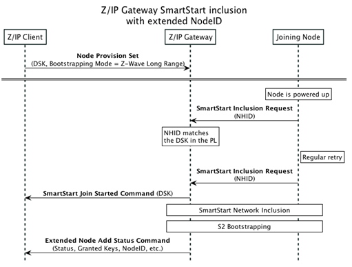
Figure 5.22 Extended NodeID SmartStart inclusion
5.2.5.14. Network management primary command class, version 1 [OBSOLETED]
\requirement{CC:0054.01.00.11.001}{8}
Warning
THIS COMMAND CLASS HAS BEEN OBSOLETED New implementations MUST NOT support this Command Class.
The Network Management Primary Command Class provides functions to pass on the primary role to another controller.
5.2.5.14.1. Controller change command
This command is used to add a controller node to the network and assign the primary controller role to the included controller.
This command has the same functionality as Node Add with the exception that the new controller will become the primary controller and the controller adding the node will become secondary.
\requirement{CC:0054.01.01.11.001}{0}
The Controller Change Status Command MUST be returned in response to this command.
\requirement{CC:0054.01.01.11.002}{0}
This command MUST NOT be issued via multicast addressing.
A receiving node MUST ignore this command if it is received via multicast addressing. The Z-Wave Multicast frame, the broadcast NodeID and the Multi Channel multi-End Point destination are all considered multicast addressing methods
7 |
6 |
5 |
4 |
3 |
2 |
1 |
0 |
|---|---|---|---|---|---|---|---|
Command Class = COMMAND_CLASS_NETWORK_MANAGEMENT_PRIMARY (0x54) |
|||||||
Command = CONTROLLER_CHANGE (0x01) |
|||||||
Seq No |
|||||||
Reserved |
|||||||
Mode |
|||||||
tx Options |
|||||||
Seq No (1 byte)
Refer to Sequence number management.
Reserved
\requirement{CC:0054.01.01.11.004}{0}
This field MUST be set to 0 by a sending node and MUST be ignored by a receiving node.
Mode (1 byte)
\requirement{CC:0054.01.01.11.005}{4}
This field is use to indicate to the receiving node if the controller change mode must be activated or de-activated. This field MUST comply with Table 5.103.
Value |
Mode identifier |
Description |
|---|---|---|
0x02 |
CONTROLLER_CHANGE_START |
Start the process of creating a new primary controller for the network |
0x05 |
CONTROLLER_CHANGE_STOP |
Stop the controller change and report a failure |
tx Options (1 byte)
\requirement{CC:0054.01.01.11.006}{2}
The tx Options field allows a controlling node to specify if transmissions MUST use special properties.. This field MUST be treated as a bitmask and MUST comply with Table 5.104
Value |
Mode identifier |
Description |
|---|---|---|
0x00 |
NULL |
Transmit at normal power level without any transmit options. |
0x02 |
TRANSMIT_OPTION_LOW_POWER |
Transmit at low output power level (1/3 of normal RF range) |
0x20 |
TRANSMIT_OPTION_EXPLORE |
Resolve new routes via explorer discovery if existing routes fail |
5.2.5.14.2. Controller change status command
This command is used to advertise the outcome of the Controller Change attempt.
7 |
6 |
5 |
4 |
3 |
2 |
1 |
0 |
|---|---|---|---|---|---|---|---|
Command Class = COMMAND_CLASS_NETWORK_MANAGEMENT_PRIMARY (0x54) |
|||||||
Command = CONTROLLER_CHANGE_STATUS (0x02) |
|||||||
Seq No |
|||||||
Status |
|||||||
Reserved |
|||||||
New NodeID |
|||||||
Node Info Length |
|||||||
List. |
Z-Wave Protocol Specific Part |
||||||
Opt. Func. |
Z-Wave Protocol Specific Part |
||||||
Basic Device Class |
|||||||
Generic Device Class |
|||||||
Specific Device Class |
|||||||
Command Class 1 *) |
|||||||
… |
|||||||
Command Class N *) |
|||||||
*) Command classes may be extended –> spanning two bytes for one command class
For fields’ description, refer to Node add status command.
5.2.5.15. Network management installation and maintenance command class, version 1
The Network Management Installation and Maintenance Command Class is used to access statistical data. Data relating to the transmission of an actual frame may be obtained via the Z/IP Packet Installation and Maintenance Header Extension.
All Transmissions / Route Information:
Packet Error Count (PEC) – Also sometimes referred to as PER. The number of unsuccessful transmissions experienced by the device.
Transmission Counter (TC) – Number of frames sent by the specified device.
Neighbors (NB) – Information on known neighbors for a specified device.
Network Management - Priority Route Set
Network Management - Priority Route Get
Network Management - Priority Route Report
5.2.5.15.1. Priority route set
This command is used to set the network route to use when sending commands to the specified NodeID.
\requirement{CC:0067.01.01.12.001}{0}
The use of this command is NOT RECOMMENDED.
7 |
6 |
5 |
4 |
3 |
2 |
1 |
0 |
|---|---|---|---|---|---|---|---|
Command Class = COMMAND_CLASS_NETWORK_MANAGEMENT_INSTALLATION_MAINTENANCE (0x67) |
|||||||
Command = PRIORITY_ROUTE_SET (0x01) |
|||||||
NodeID |
|||||||
Repeater 1 [First repeater] |
|||||||
Repeater 2 |
|||||||
Repeater 3 |
|||||||
Repeater 4 [Last repeater] |
|||||||
Speed |
|||||||
NodeID (1 byte)
\requirement{CC:0067.01.01.11.001}{0}
This field is used to specify the destination NodeID for which a last working route MUST be set.
Repeater (4 bytes)
This field is used to specify repeaters for the route. Each byte represents a NodeID and the first field (Repeater 1) is the first repeater of the route.
\requirement{CC:0067.01.01.11.002}{0}
The value 0x00 MUST indicate that the byte does not represent a repeater. If the route is shorter than four repeaters, unused repeaters fields MUST be set to 0x00. If Repeater 1 is set to 0x00, it means that the Last Working Route is direct (nodes are within direct reach).
Speed (1 byte)
\requirement{CC:0067.01.01.11.003}{0}
This field is used to indicate which speed MUST be used for the route. This field MUST comply with Table 5.107.
Value |
Speed |
|---|---|
0x01 |
9.6 kbit/sec |
0x02 |
40 kbit/sec |
0x03 |
100 kbit/sec |
5.2.5.15.2. Priority route get
This command is used to query the current network route from a node for a given destination.
\requirement{CC:0067.01.02.11.001}{0}
The Priority Route Report MUST be returned in response to this command.
\requirement{CC:0067.01.02.11.002}{0}
This command MUST NOT be issued via multicast addressing.
\requirement{CC:0067.01.02.11.003}{0}
A receiving node MUST NOT return a response if this command is received via multicast addressing. The Z-Wave Multicast frame, the broadcast NodeID and the Multi Channel multi-End Point destination are all considered multicast addressing methods.
7 |
6 |
5 |
4 |
3 |
2 |
1 |
0 |
|---|---|---|---|---|---|---|---|
Command Class = COMMAND_CLASS_NETWORK_MANAGEMENT_INSTALLATION_MAINTENANCE (0x67) |
|||||||
Command = PRIORITY_ROUTE_GET (0x02) |
|||||||
NodeID |
|||||||
NodeID (1 byte)
This field is used to specify the NodeID destination for which the current network route is requested.
5.2.5.15.3. Priority route report
This command is used to advertise the current network route in use for an actual destination NodeID.
7 |
6 |
5 |
4 |
3 |
2 |
1 |
0 |
|---|---|---|---|---|---|---|---|
Command Class = COMMAND_CLASS_NETWORK_MANAGEMENT_INSTALLATION_MAINTENANCE (0x67) |
|||||||
Command = PRIORITY_ROUTE_REPORT (0x03) |
|||||||
NodeID |
|||||||
Type |
|||||||
Repeater 1 - 1 [First repeater] |
|||||||
Repeater 2 – 1 |
|||||||
Repeater 3 – 1 |
|||||||
Repeater 4 - 1 [Last repeater] |
|||||||
Speed -1 |
|||||||
Type (1 byte)
\requirement{CC:0067.01.03.11.001}{0}
This field is used to indicate the route type. It MUST comply with Table 5.110. A node MUST return the route with the highest priority value if several routes are available at the node.
\requirement{CC:0067.01.03.11.002}{20}
Value |
Identifier |
Description |
Priority |
|---|---|---|---|
0x00 |
– |
There is no route defined for the target NodeID. In this case, the Repeater and Speed fields MUST be set to 0x00 and ignored by a receiving node. |
4 (lowest) |
0x01 |
ZW_PRIORITY_ROUTE_ZW_LWR |
The returned route is a last working route. The Last Working route is the last successful route used between the sender and receiver. |
2 |
0x02 |
ZW_PRIORITY_ROUTE_ZW_NLWR |
The returned route is a next to last working route. It is a route which was Last Working Route and has been replaced by a new route. |
3 |
0x10 |
ZW_PRIORITY_ROUTE_APP_PR |
The returned has been determined by the application |
1 (highest) |
Repeater (4 bytes)
Refer to Priority route set.
Speed (1 byte)
Refer to Priority route set.
5.2.5.15.4. Statistics get
This command is used to query Installation and Maintenance statistics from a node.
\requirement{CC:0067.01.04.11.001}{0}
The Statistics Report MUST be returned in response to this command.
\requirement{CC:0067.01.04.11.002}{0}
This command MUST NOT be issued via multicast addressing.
\requirement{CC:0067.01.04.11.003}{0}
A receiving node MUST NOT return a response if this command is received via multicast addressing. The Z-Wave Multicast frame, the broadcast NodeID and the Multi Channel multi-End Point destination are all considered multicast addressing methods.
7 |
6 |
5 |
4 |
3 |
2 |
1 |
0 |
|---|---|---|---|---|---|---|---|
Command Class = COMMAND_CLASS_NETWORK_MANAGEMENT_INSTALLATION_MAINTENANCE (0x67) |
|||||||
Command = STATISTICS_GET (0x04) |
|||||||
NodeID |
|||||||
NodeID (1 byte)
This field is used to specify the NodeID for which statistics are requested.
5.2.5.15.5. Statistics report
This command is used to report Installation and Maintenance statistics recorded by a node.
7 |
6 |
5 |
4 |
3 |
2 |
1 |
0 |
|---|---|---|---|---|---|---|---|
Command Class = COMMAND_CLASS_NETWORK_MANAGEMENT_INSTALLATION_MAINTENANCE (0x67) |
|||||||
Command = STATISTICS_REPORT (0x05) |
|||||||
NodeID |
|||||||
Statistics – Type 1 |
|||||||
Statistics – Length 1 |
|||||||
Statistics – Value 1 |
|||||||
… |
|||||||
Statistics – Type N |
|||||||
Statistics – Length N |
|||||||
Statistics – Value N |
|||||||
NodeID (1 byte)
\requirement{CC:0067.01.04.11.004}{0}
This field MUST carry the same value as received in the Statistics Get Command.
Statistics (N bytes)
\requirement{CC:0067.01.04.11.005}{0} \requirement{CC:0067.01.04.13.001}{4}
The statistics field MUST be formatted as cascaded Type-Length-Value (TLV) structures. The Z/IP Gateway MAY send any combination of TLV structures. Valid types are shown in Table 5.113.
Name |
Statistics - Type |
Statistics - Length (Bytes) |
|---|---|---|
Route Changes (RC) |
0 |
1 |
Transmission Count (TC) |
1 |
1 |
Neighbors (NB) |
2 |
n |
Packet Error Count (PEC) |
3 |
1 |
Sum of transmission times (TS) |
4 |
4 |
Sum of transmission times squared (TS2) |
5 |
4 |
\requirement{CC:0067.01.04.11.006}{0}
All other values are reserved and MUST NOT be used by a sending node. Reserved values MUST be ignored by a receiving node.
5.2.5.15.5.1. Route changes (RC)
7 |
6 |
5 |
4 |
3 |
2 |
1 |
0 |
|---|---|---|---|---|---|---|---|
Statistics - Type = 0x00 |
|||||||
Statistics – Length = 1 |
|||||||
Statistics – Value = Route Changes |
|||||||
Route Changes (1 byte)
The RC field is used to advertise the number of routing attempts needed to reach a destination. The number is a combination of Last Working Route (LWR) changes and Jitter measurements during transmission attempts between the Z/IP Gateway and the Z-Wave device.
RC is incremented automatically by the Z/IP Gateway when either of the below conditions are true:
Last Working Route changed from the transmission of one command to the next
\(T_n\) - \(T_{n-1}\) > 150ms where \(T_n\) and \(T_{n-1}\) = the time needed to complete a transmission of a command
IF 2 channel and FLIRS node, RC: \(T_n = T_n\) mod 1100
IF 3 channel and FLIRS node, RC cannot increment based on time calculation
5.2.5.15.5.2. Transmission Count (TC)
7 |
6 |
5 |
4 |
3 |
2 |
1 |
0 |
|---|---|---|---|---|---|---|---|
Statistics - Type = 0x01 |
|||||||
Statistics – Length = 1 |
|||||||
Statistics – Value = Transmission Count |
|||||||
Transmission Count (1 byte)
Total number of transmissions sent by all Z/IP Clients through the Z/IP GW to the specified Z-Wave destination node.
5.2.5.15.5.3. Neighbors (NB)
7 |
6 |
5 |
4 |
3 |
2 |
1 |
0 |
|---|---|---|---|---|---|---|---|
Statistics - Type = 0x02 |
|||||||
Statistics – Length = N * 2 |
|||||||
Statistics – Value = NodeID 1 |
|||||||
Statistics – Value = Repeater 1 |
Reserved |
Statistics – Value = Speed 1 |
|||||
… |
|||||||
Statistics – Value = NodeID N |
|||||||
Statistics – Value = Repeater N |
Reserved |
Statistics – Value = Speed N |
|||||
NodeID (N * 1 byte)
The NodeID of the actual neighbor.
Speed (N * 4 bits)
Value |
Speed |
|---|---|
0x01 |
9.6 kbit/sec |
0x02 |
40 kbit/sec |
0x04 |
100 kbit/sec |
\requirement{CC:0067.01.04.11.007}{0}
All other values are reserved and MUST NOT be used by a sending node. Reserved values MUST be ignored by a receiving node.
Repeater (N * 1 bit)
If this bit is set then the node is a repeater.
5.2.5.15.5.4. Packet error count (PEC)
7 |
6 |
5 |
4 |
3 |
2 |
1 |
0 |
|---|---|---|---|---|---|---|---|
Statistics - Type = 0x03 |
|||||||
Statistics – Length = 1 |
|||||||
Statistics – Value = Packet Error Count |
|||||||
Packet Error Count (1 byte)
\requirement{CC:0067.01.04.11.008}{0}
Also sometimes referred to as PER. PEC is measured by the Gateway. The PEC value MUST be incremented each time the Gateway detects a failing transmission for each specific Z-Wave destination node.
Sum of transmission times (TS)
7 |
6 |
5 |
4 |
3 |
2 |
1 |
0 |
|---|---|---|---|---|---|---|---|
Statistics - Type = 0x04 |
|||||||
Statistics – Length = 4 |
|||||||
Statistics – Value = Sum of transmission times 1 (MSB) |
|||||||
Statistics – Value = Sum of transmission times 2 |
|||||||
Statistics – Value = Sum of transmission times 3 |
|||||||
Statistics – Value = Sum of transmission times 4 (LSB) |
|||||||
Sum of transmission times (4 bytes)
The sum of all transmission times. This may be used to calculate the average transmission time. The time is given as a 32-bit unsigned integer MSB in milliseconds.
Where N is the number of transmissions.
5.2.5.15.5.5. Sum of transmission times squared (TS2)
7 |
6 |
5 |
4 |
3 |
2 |
1 |
0 |
|---|---|---|---|---|---|---|---|
Statistics - Type = 0x05 |
|||||||
Statistics – Length = 4 |
|||||||
Statistics – Value = Sum of transmission times squared 1 (MSB) |
|||||||
Statistics – Value = Sum of transmission times squared 2 |
|||||||
Statistics – Value = Sum of transmission times squared 3 |
|||||||
Statistics – Value = Sum of transmission times squared 4 (LSB) |
|||||||
Sum of transmission times squared (4 bytes)
The sum of the square of all transmission times. This may be used to calculate the variance of the transmission time. The time is given as a 32 bit unsigned integer MSB in milliseconds^2.
The Variance may be calculated as follows:
(König-Huygens theorem)
Where N is the number of transmissions.
A high variance is a sign of a bad link.
5.2.5.15.6. Statistics clear
This command is used to clear all statistic registers maintained by the node.
7 |
6 |
5 |
4 |
3 |
2 |
1 |
0 |
|---|---|---|---|---|---|---|---|
Command Class = COMMAND_CLASS_NETWORK_MANAGEMENT_INSTALLATION_MAINTENANCE (0x67) |
|||||||
Command = STATISTICS_CLEAR (0x06) |
|||||||
A receiving node MUST set all counters to 0.
5.2.5.15.7. Use cases
5.2.5.15.7.1. Intranode network management: TV OSD system controlling lamps
Intranode network management is the process close to Z-Wave API programming. No messages ever leave the device. Messages only flow between different software modules.
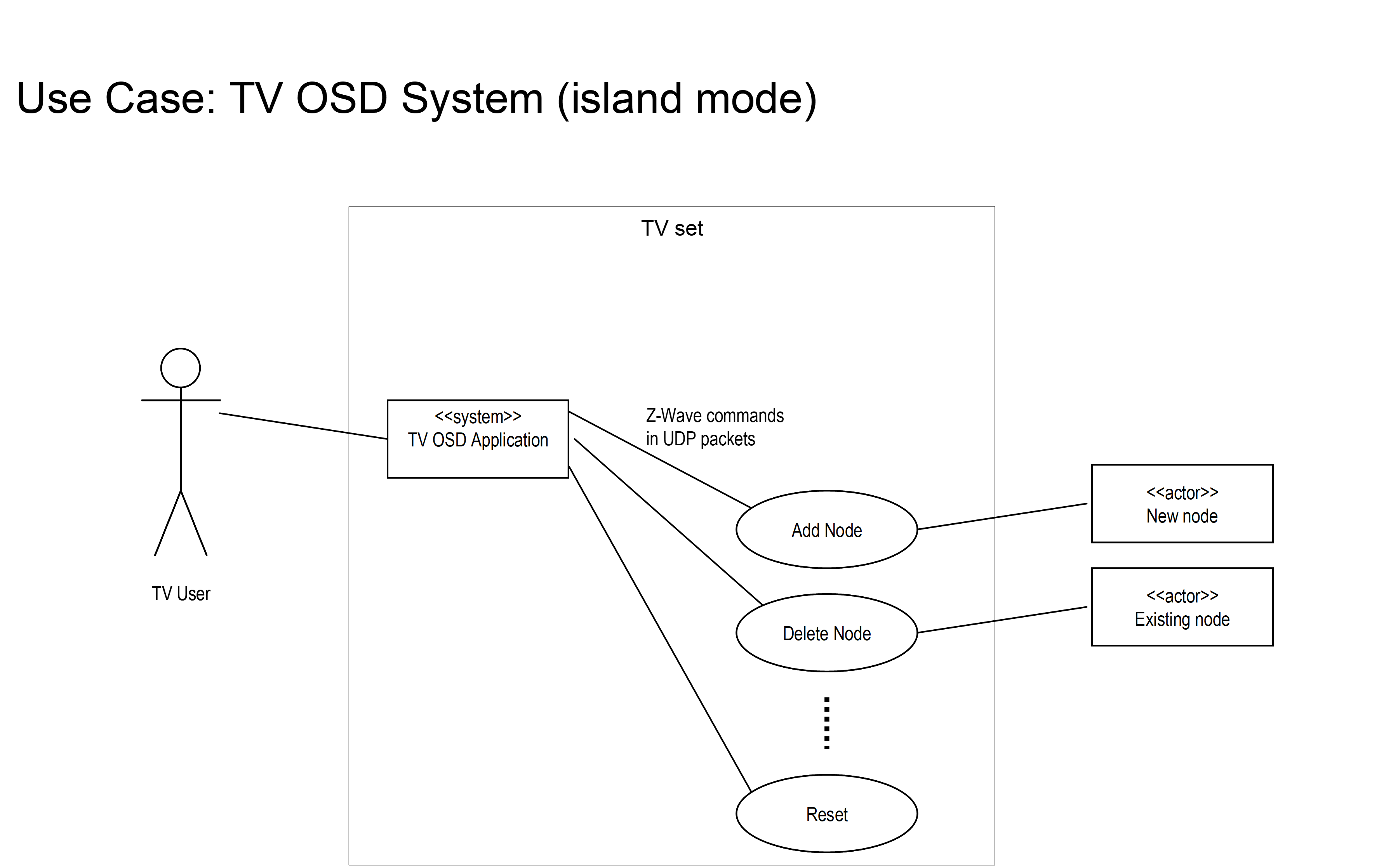
Figure 5.23 TV OSD System controlling lamps
Using UDP/IP for carrying the messages allows for a simple integration interface between applications designed by different partners.
5.2.5.15.7.2. Intranet network management: remote controlling a primary controller
Intranet network management extends the use of command messages to separate physical devices. Messages flow between software modules but the modules reside in separate physical entities having individual IP addresses – or at least separate NodeIDs.
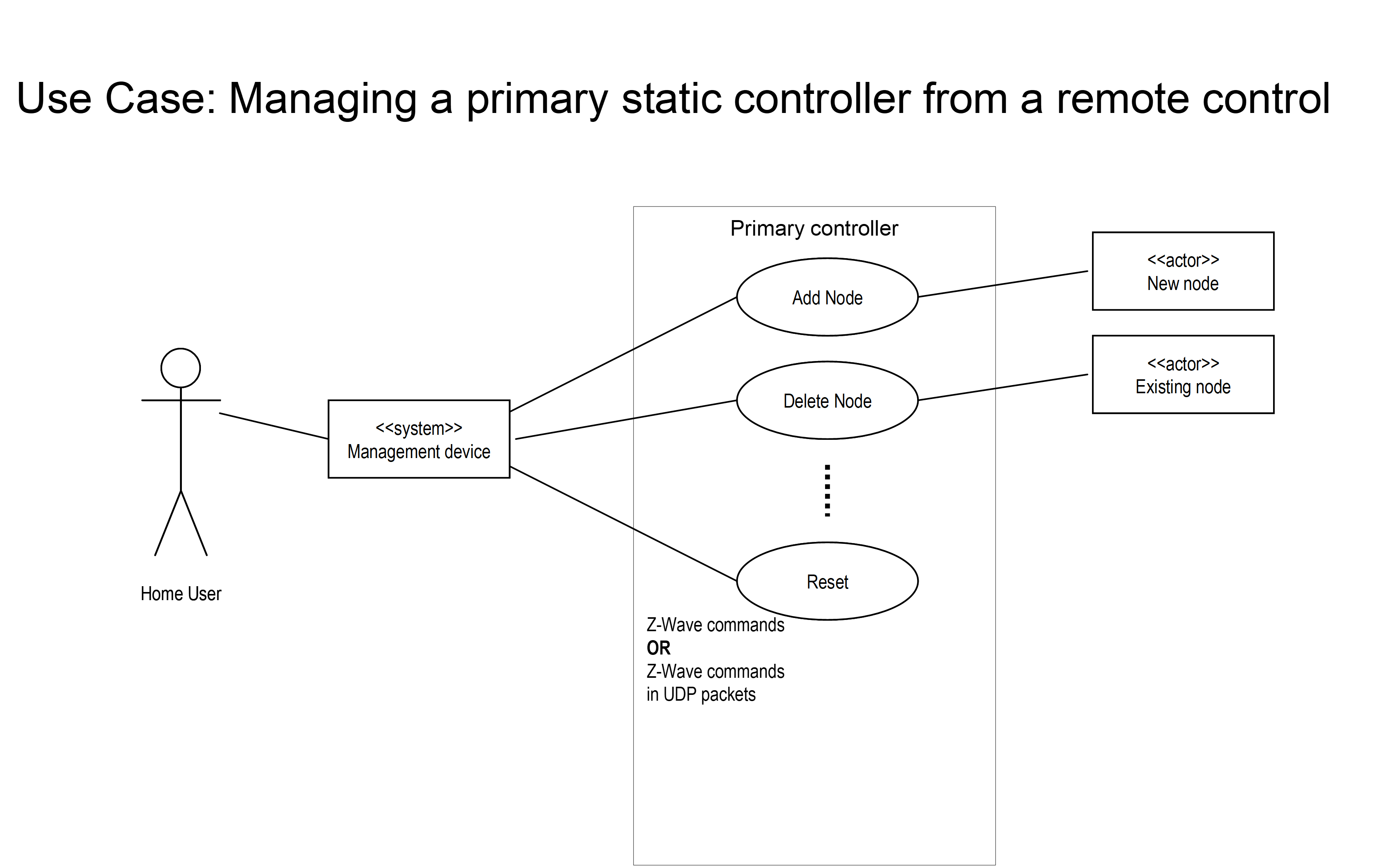
Figure 5.24 Managing a primary static controller from a remote control
Network management via messages allows for sophisticated interfaces to the primary controller of a network. Controllers with SUC/SIS capability may also leverage from the Network Management command classes.
5.2.5.15.7.3. Internet network management #1: call-center support for TV OSD user
Internet network management uses the same command messages. Messages flow between software modules but the modules reside in separate physical entities in a non-trusted environment such as the Internet. Remote access technologies should be used to protect the communication.
In this use case a TV user may call the service provider for support in adding a new lamp to the network.
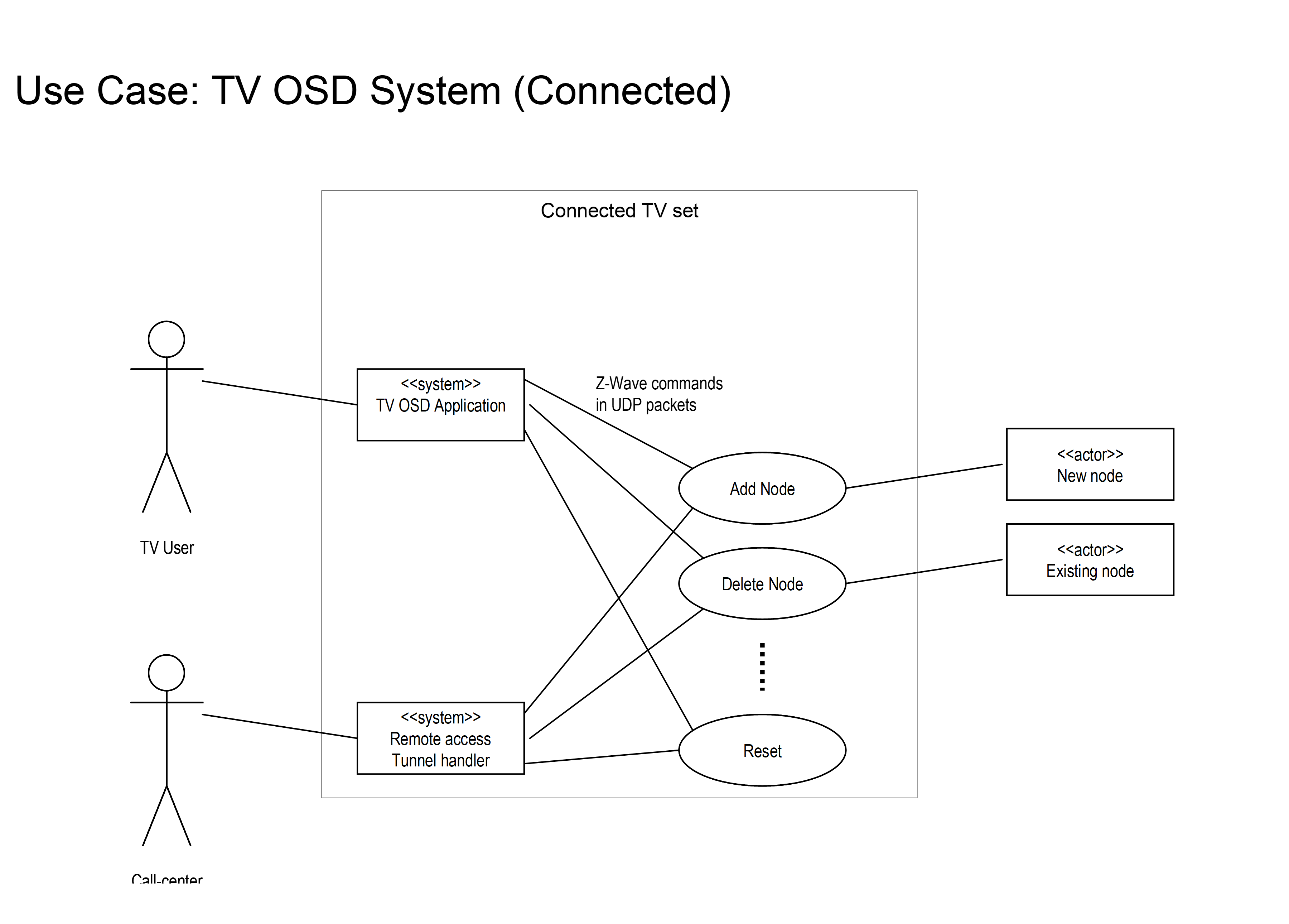
Figure 5.25 TV OSD System
Internet network management #2: remote management of Z/IP network
In this use case a user may use an IP based home control management system running in the LAN for setting up the Z/IP network. The user may use normal UDP transport in the LAN environment. Due to the critical nature of the network management command classes the user however should use remote access protection technologies over LAN as well as over Internet. The benefit of designing a home control system using remote access protection by default is that it may be moved from a location in the LAN to any place in the Internet and work completely unaffected.
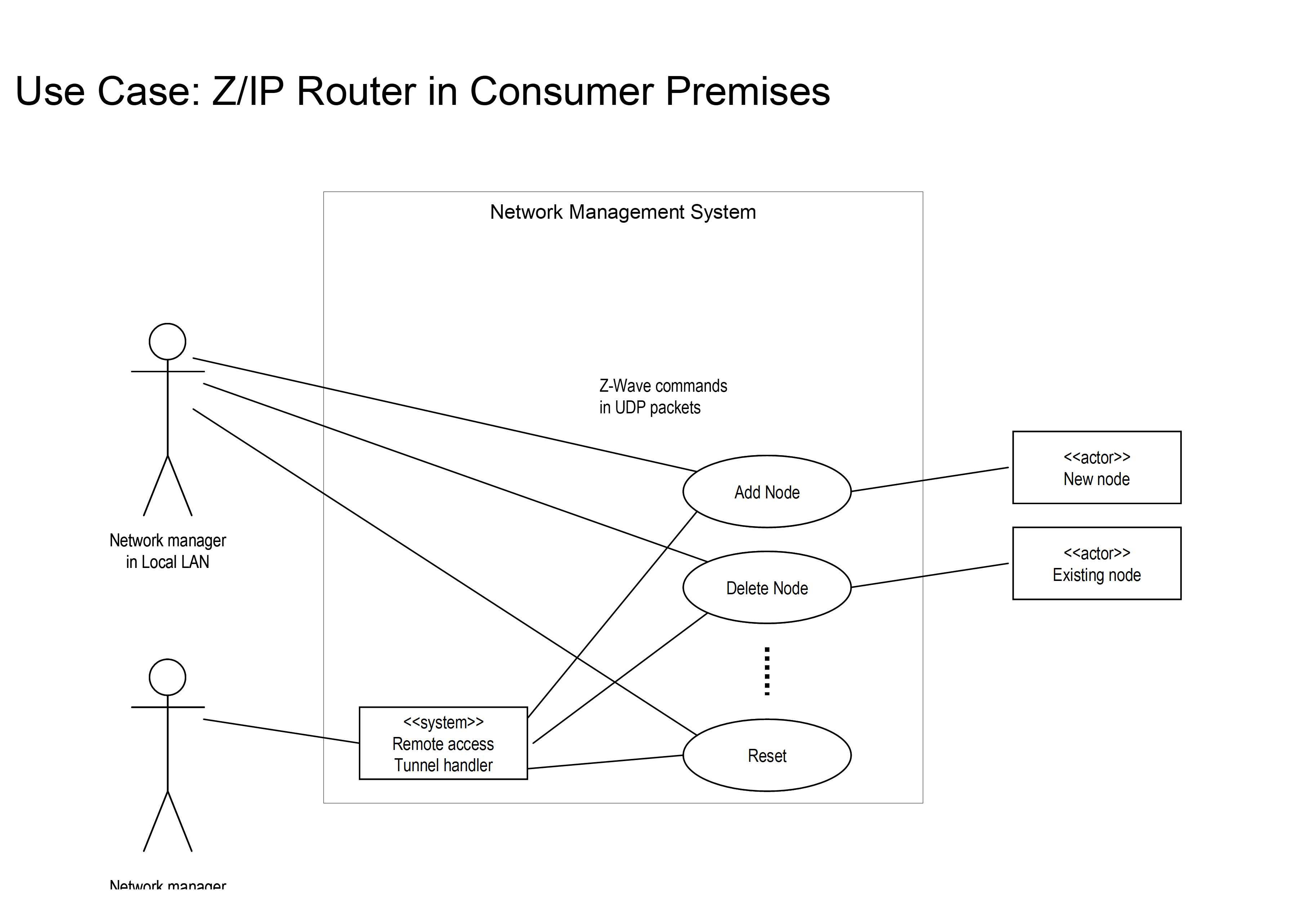
Figure 5.26 Z/IP Router in consumer premises
5.2.5.15.7.4. Traffic flow: gathering node information
The following sequence diagram introduces a new concept of gathering Node Information.
The node list provides an overview of the nodes in the network; as good as the Z/IP gateway can provide this information. Using that node list, the requesting host may request information on individual nodes from the Z/IP Gateway. The ”Node Info Cached Get” command reports all supported and controlled classes.
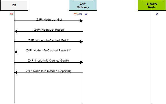
Figure 5.27 Gathering node information
5.2.5.16. Network management installation and maintenance command class, version 2
5.2.5.16.1. Compatibility considerations
The Network Management Installation and Maintenance Command Class, version 2 is backwards compatible with the Network Management Installation and Maintenance Command Class, version 1.
\requirement{CC:0067.02.01.21.002}{0}
All commands and fields not mentioned in this version MUST remain unchanged from version 1.
The following commands have been added to allow a supporting node to report the RSSI it measured in each channel of the network:
RSSI Get Command
RSSI Report Command
5.2.5.16.2. RSSI get command
This command is used to query the measured RSSI on the Z-Wave network from a node.
\requirement{CC:0067.02.07.11.001}{0}
The RSSI Report Command MUST be returned in response to this command.
\requirement{CC:0067.02.07.11.002}{0}
This command MUST NOT be issued via multicast addressing.
\requirement{CC:0067.02.07.11.003}{0}
A receiving node MUST NOT return a response if this command is received via multicast addressing. The Z-Wave Multicast frame, the broadcast NodeID and the Multi Channel multi-End Point destination are all considered multicast addressing methods.
7 |
6 |
5 |
4 |
3 |
2 |
1 |
0 |
|---|---|---|---|---|---|---|---|
Command Class = COMMAND_CLASS_NETWORK_MANAGEMENT_INSTALLATION_MAINTENANCE (0x67) |
|||||||
Command = RSSI_GET (0x07) |
|||||||
5.2.5.16.3. RSSI report command
This command is used to advertise the measured RSSI on the Z-Wave network for each used channel.
7 |
6 |
5 |
4 |
3 |
2 |
1 |
0 |
|---|---|---|---|---|---|---|---|
Command Class = COMMAND_CLASS_NETWORK_MANAGEMENT_INSTALLATION_MAINTENANCE (0x67) |
|||||||
Command = RSSI_REPORT (0x08) |
|||||||
Channel 1 RSSI |
|||||||
Channel 2 RSSI |
|||||||
Channel 3 RSSI |
|||||||
Channel 1 RSSI (8 bits)
\requirement{CC:0067.02.08.11.001}{0}
This field MUST carry the measured RSSI value on channel 1.
\requirement{CC:0067.02.08.11.002}{0}
This field MUST be encoded as using signed representation in the dBm unit and according to Table 5.124.
Channel 2 RSSI (8 bits)
\requirement{CC:0067.02.08.11.003}{0}
This field MUST carry the measured RSSI value on channel 2.
\requirement{CC:0067.02.08.11.004}{0}
This field MUST be encoded as using signed representation in the dBm unit and according to Table 5.124.
Channel 3 RSSI (8 bits)
\requirement{CC:0067.02.08.11.005}{0}
This field MUST carry the measured RSSI value on channel 3, if applicable.
\requirement{CC:0067.02.08.11.006}{0}
This field MUST be encoded as using signed representation in the dBm unit and according to Table 5.124.
Value(signed) |
Description |
|---|---|
127 (0x7F) |
RSSI_NOT_AVAILABLE. This value is returned for unused channels or if no RSSI measurement is available. |
126 (0x7E) |
RSSI_MAX_POWER_SATURATED This value is returned if the measured RSSI is above the maximum power. |
125 (0x7D) |
RSSI_BELOW_SENSITIVITY. This value is returned if the measured RSSI is below the receiver’s sensitivity. |
-32..-128 (0xE0..0x80) |
These values represent the actual RSSI measurement value from respectively -32 dBm to -128 dBm |
\requirement{CC:0067.02.08.11.007}{0}
All other values are reserved and MUST NOT be used by a sending node. Reserved values MUST be ignored by a receiving node.
5.2.5.17. Network management installation and maintenance command class, version 3
5.2.5.17.1. Compatibility considerations
The Network Management Installation and Maintenance Command Class, version 3 is backwards compatible with the Network Management Installation and Maintenance Command Class, version 2.
All commands and fields, that are not mentioned in this version MUST remain unchanged from version 2.
The following command has been added to notify the Z/IP Client application the occurrence of S2 Nonce Resynchronization event, (including extended NodeID support) :
S2 Resynchronization Event Command
The following commands are introduced to support extended NodeIDs:
Extended Statistics Get
Extended Statistics Report
5.2.5.17.2. S2 resynchronization event command
This command is used to notify the Z/IP Client application the occurrence of S2 Nonce Resynchronization event. This will allow the client application to recover faster from a synchronization error that may cause message delay and loss.
The Z/IP Gateway MUST send this command to the Unsolicited destinations when the Gateway received Nonce Report with SOS flag equal to 1 while Verify Delivery to the sending node is inactive.
The Z/IP Gateway MUST NOT send this command in the following cases:
The Z/IP Gateway received the Nonce Report with SOS flag equals to 1 and Verify Delivery to sending node is active.
The Z/IP Gateway received the Nonce Report with SOS flag equals to 1 and the ZIP NAK is sent to the Z/IP Client application.
The Z/IP Gateway received the Nonce Report with SOS flag equals to 1 when the sending node cannot decrypt the frame sent from the Gateway.
The Z/IP Gateway received Nonce Get (i.e., node coming out of power reset.
7 |
6 |
5 |
4 |
3 |
2 |
1 |
0 |
|---|---|---|---|---|---|---|---|
Command Class = COMMAND_CLASS_NETWORK_MANAGEMENT_INSTALLATION_MAINTENANCE (0x67) |
|||||||
Command = S2_RESYNCHRONIZATION_EVENT (0x09) |
|||||||
NodeID |
|||||||
Reason |
|||||||
Extended NodeID (MSB) |
|||||||
Extended NodeID (LSB) |
|||||||
NodeID (8 bits)
The NodeID field contains the NodeID of the peer node triggering a nonce resynchronization.
This field MUST be set to 0xFF if the NodeID triggering a nonce resynchronization is greater than 255.
Reason (8 bits)
The reason field contains the detailed reason for the Resynchronization event. This field MUST encoded as described in Table 5.126. This field MUST use signed encoding.
Value |
Description |
|---|---|
0 |
SOS_EVENT_REASON_UNANSWERED A Nonce Report with SOS equals to 1 was received at an unexpected time and no response was sent. Application may use this information to abort Supervision Report timeout if the remote NodeID matches. The Nonce Report was unanswered because the retransmission was performed while the S2 layer was idle or transmitting to another NodeID. In this case, a frame to NodeID was most likely lost. If the ZIP Client had only one frame outstanding with NodeID, it can safely be assumed that the frame was lost. Note: Supervision Encapsulation should be used to acknowledge outstanding frames. |
-127..-1 |
Reserved |
1..127 |
Reserved |
Extended NodeID (2 bytes)
This field is used to advertise the NodeID of the peer node triggering a nonce resynchronization.
This field MUST be set to the actual NodeID that was triggered a Nonce resynchronization.
5.2.5.17.3. Extended statistics get
This command is used to query Installation and Maintenance statistics from a node.
The Extended Statistics Report MUST be returned in response to this command.
This command MUST NOT be issued via multicast addressing.
A receiving node MUST NOT return a response if this command is received via multicast addressing. The Z-Wave Multicast frame, the broadcast NodeID and the Multi Channel multi-End Point destination are all considered multicast addressing methods.
7 |
6 |
5 |
4 |
3 |
2 |
1 |
0 |
|---|---|---|---|---|---|---|---|
Command Class = COMMAND_CLASS_NETWORK_MANAGEMENT_INSTALLATION_MAINTENANCE (0x67) |
|||||||
Command = EXTENDED_STATISTICS_GET (0x0B) |
|||||||
Extended NodeID (MSB) |
|||||||
Extended NodeID (LSB) |
|||||||
Extended NodeID (2 bytes)
This field is used to specify the NodeID for which statistics are requested. A receiving node MUST return a report for the NodeID indicated in this field.
5.2.5.17.4. Extended statistics report
7 |
6 |
5 |
4 |
3 |
2 |
1 |
0 |
|---|---|---|---|---|---|---|---|
Command Class = COMMAND_CLASS_NETWORK_MANAGEMENT_INSTALLATION_MAINTENANCE (0x67) |
|||||||
Command = EXTENDED_STATISTICS_REPORT (0x0C) |
|||||||
Extended NodeID (MSB) |
|||||||
Extended NodeID (LSB) |
|||||||
Statistics – Type 1 |
|||||||
Statistics – Length 1 |
|||||||
Statistics – Value 1 |
|||||||
… |
|||||||
Statistics – Type N |
|||||||
Statistics – Length N |
|||||||
Statistics – Value N |
|||||||
NodeID (2 bytes)
This field is used to advertise the NodeID for which statistics are advertised. No TLV MUST be appended for non-existing NodeIDs or if no statistics have been saved for the advertised NodeID.
Statistics (N bytes)
The statistics field MUST be formatted as cascaded Type-Length-Value (TLV) structures. The Z/IP Gateway MAY send any combination of TLV structures. Valid types are shown in Table 5.113 and described in section Statistics report.
5.2.5.18. Network management installation and maintenance command class, version 4
5.2.5.18.1. Compatibility considerations
The Network Management Installation and Maintenance Command Class, version 4 is backwards compatible with the Network Management Installation and Maintenance Command Class, version 3.
All commands and fields not mentioned in this version MUST remain unchanged from version 3.
The following commands have been added to allow a supporting node to configure the channel to use for Z-Wave Long Range:
Z-Wave Long Range Channel Configuration Set
Z-Wave Long Range Channel Configuration Get
Z-Wave Long Range Channel Configuration Report
The following commands have been extended to allow a supporting node to report the RSSI it measured in the Z-Wave Long Range channel of the network:
RSSI Report Command
5.2.5.18.2. RSSI report command
This command is used to advertise the measured RSSI on the Z-Wave network for each used channel.
7 |
6 |
5 |
4 |
3 |
2 |
1 |
0 |
|---|---|---|---|---|---|---|---|
Command Class = COMMAND_CLASS_NETWORK_MANAGEMENT_INSTALLATION_MAINTENANCE (0x67) |
|||||||
Command = RSSI_REPORT (0x08) |
|||||||
Channel 1 RSSI |
|||||||
Channel 2 RSSI |
|||||||
Channel 3 RSSI |
|||||||
Z-Wave Long Range Primary Channel RSSI |
|||||||
Z-Wave Long Range Secondary Channel RSSI |
|||||||
Fields not described below MUST remain unchanged from version 3.
Z-Wave Long Range Primary Channel RSSI (8 bits)
This field MUST carry the measured RSSI value on the Z-Wave Long Range Primary Channel.
This field MUST be encoded as using signed representation in the dBm unit and according to Table 5.124.
Z-Wave Long Range Secondary Channel RSSI (8 bits)
This field MUST carry the measured RSSI value on the Z-Wave Long Range Secondary Channel.
This field MUST be encoded as using signed representation in the dBm unit and according to Table 5.124.
5.2.5.18.3. Z-Wave long range channel configuration set
This command is used to configure which channel to use for the Z-Wave Long Range protocol.
7 |
6 |
5 |
4 |
3 |
2 |
1 |
0 |
|---|---|---|---|---|---|---|---|
Command Class = COMMAND_CLASS_NETWORK_MANAGEMENT_INSTALLATION_MAINTENANCE (0x67) |
|||||||
Command = ZWAVE_LR_CHANNEL_CONFIGURATION_SET (0x0A) |
|||||||
Z-Wave Long Range Channel |
|||||||
Z-Wave Long Range Channel (8 bits)
This field is used to specify which channel to use for Z-Wave Long Range.
The value 0x01 MUST indicate to use the Primary Z-Wave Long Range Channel.
The value 0x02 MUST indicate to use the Secondary Z-Wave Long Range Channel.
All other values are reserved.
5.2.5.18.4. Z-Wave long range channel configuration get
This command is used to request the currently configured Z-Wave Long Range Channel.
The Z-Wave Long Range Channel Configuration Report MUST be returned in response to this command.
This command MUST NOT be issued via multicast addressing.
A receiving node MUST NOT return a response if this command is received via multicast addressing. The Z-Wave Multicast frame, the broadcast NodeID and the Multi Channel multi-End Point destination are all considered multicast addressing methods.
7 |
6 |
5 |
4 |
3 |
2 |
1 |
0 |
|---|---|---|---|---|---|---|---|
Command Class = COMMAND_CLASS_NETWORK_MANAGEMENT_INSTALLATION_MAINTENANCE (0x67) |
|||||||
Command = ZWAVE_LR_CHANNEL_CONFIGURATION_GET (0x0D) |
|||||||
5.2.5.18.5. Z-Wave long range channel configuration report
This command is used to advertise the configured Z-Wave Long Range Channel.
7 |
6 |
5 |
4 |
3 |
2 |
1 |
0 |
|---|---|---|---|---|---|---|---|
Command Class = COMMAND_CLASS_NETWORK_MANAGEMENT_INSTALLATION_MAINTENANCE (0x67) |
|||||||
Command = ZWAVE_LR_CHANNEL_CONFIGURATION_REPORT (0x0E) |
|||||||
Z-Wave Long Range Channel |
|||||||
Z-Wave Long Range Channel (8 bits)
This field is used to advertise the channel to use for Z-Wave Long Range.
The value 0x01 MUST indicate to use the Primary Z-Wave Long Range Channel.
The value 0x02 MUST indicate to use the Secondary Z-Wave Long Range Channel.
All other values are reserved.
A supporting node SHOULD use the Primary Z-Wave Long Range Channel by default.