2.2.11. Authentication Command Class, version 1 [NEVER CERTIFIED]
Warning
THIS COMMAND CLASS HAS NEVER BEEN CERTIFIED
This command class has never been implemented and certified by a Z-Wave product
Therefore, this Command Class definition MAY be updated in a non-backwards
compatible manner, or even removed.
Consult with the Z-Wave Alliance Application Work Group if you consider
implementing this Command Class.
Authentication Command Class is a generic Command Class which can be used for
transporting different technology authentication data contents
(e.g., RFID, Magnetic Cards, etc.) in a Z-Wave network for access control systems.
Authentication Data contents are initialized on a supporting node using a unique Authentication Data ID. Each Authentication Data ID also has an Authentication Technology Type, representing the input or technology with which the Authentication Data can be used. A user having access with several types of input technologies will have a Data Identifier for each of the technologies.
A node may support one or more authentication technologies including User Code. Combination of valid sets of Authentication Data can be configured on a supporting node using a unique Authentication ID. The Authentication ID will for example allow a user only if he/she inputs both an RFID tag and the corresponding User Code. An actual user may be associated with several Authentication IDs.
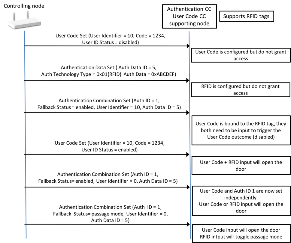
An example of Authentication Data ID and Authentication ID configurations are described in Figure 2.4.
A node may support a Checksum functionality. A controlling node can request a checksum representing all authentication data content (either Authentication IDs or Authentication Data IDs) defined at the supporting node to ensure that the authentication data content databases are synchronized.
This Command Class can be used in conjunction with the Entry Control Command Class, to report the Authentication Data input to a controlling application.
This Command Class can be used in conjunction with the Door Lock Command Class or Barrier Operator Command Class. In this case, a supporting node MUST reflect Authentication Data inputs in the door lock status when relevant. (e.g. when the door becomes unsecured by Authentication Data input, the Door Lock Operation mode is updated to unsecure with an optional timeout).
A node supporting this Command Class MAY have an Association group issuing the corresponding Door Lock Operation Set Commands or Basic Set Commands when there are a valid Authentication Data input in order to control other door locks.
A supporting node may support several authentication technologies such as User Code, RFID, Cards and etc. A combination these technologies may also be needed to get access. In this case, a supporting node can be configured to accept certain combinations of authentication technologies.
An assigned User Code in the User Code Command Class may be part of an Authentication ID. In this case, all the Authentication credentials (including the User Code) defined in the Authentication ID MUST be input at the node in order to trigger the outcome defined by the User Code Status.
In other words, the User Code input alone is no longer enough, it will require all the credentials defined in the Authentication ID to get access. An example is given in Figure 2.3.
This command is used to request the Authentication technology capabilities, number of Authentication ID and Data ID supported by the receiving node.
The Authentication Capability Report Command MUST be returned in response to this command.
This command MUST NOT be issued via multicast addressing.
A receiving node MUST NOT return a response if this command is received via multicast addressing. The Z-Wave Multicast frame, the broadcast NodeID and the Multi Channel multi-End Point destination are all considered multicast addressing methods.
Command Class = COMMAND_CLASS_AUTHENTICATION (0xA1)
Command = AUTHENTICATION_CAPABILITY_REPORT (0x02)
Supported Data ID Entries (MSB)
Supported Data ID Entries (LSB)
Supported Authentication ID Entries (MSB)
Supported Authentication ID Entries (LSB)
MAR
MADR
OR
Reserved
Supported Authentication Technology
Type Bit Mask length
Supported Authentication Technology Type Bit Mask 1
…
Supported Authentication Technology Type Bit Mask N
Supported Checksum Type Bit Mask
Reserved
Supported Fallback Status Bit Mask length
Supported Fallback Status Bit Mask 1
…
Supported Fallback Status Bit Mask N
Reserved
This field MUST be set to 0 by a sending node and MUST be ignored by a receiving node.
Supported Data ID Entries (16 bits)
This field is used to advertise the number of supported Authentication Data ID Entries.
The first byte MUST carry the most significant byte of the 16 bits value.
This field MUST be set to the total amount of supported Authentication Data IDs. This field MUST be in the range 1…65535.
Supported Authentication ID Entries (16 bits)
This field is used to advertise the number of supported Authentication ID Entries.
The first byte MUST carry the most significant byte of the 16 bits value.
This field MUST be set to the total amount of supported combinations entries. This field MUST be in the range 1…65535.
MAR (Multiple Authentication ID Report) Support (1 bit)
This field indicates if the sending node supports reporting the Multiple Authentication ID Blocks at once in a single Authentication Technologies Combination Report Command. This functionality should be supported by node supporting large amount of Authentication ID Entries.
The value 1 MUST indicate that the Multiple Authentication ID Report functionality is supported.
The value 0 MUST indicate that the Multiple Authentication ID Report functionality is not supported.
MADR (Multiple Authentication Data ID Report) Support (1 bit)
This field indicates if the sending node supports reporting the Multiple Authentication Data ID Blocks at once in a single Authentication Data Report Command. This functionality should be supported by node supporting large amount of Authentication Data ID Entries.
The value 1 MUST indicate that the Multiple Authentication Data ID Report functionality is supported.
The value 0 MUST indicate that the Multiple Authentication Data ID Report functionality is not supported.
OR Support (1 bit)
This field is used to advertise if the node supports being set Authentication ID combinations using a OR logic (User Code OR Authentication data ID 1 OR … OR Authentication data ID N)
The value 1 MUST indicate that the OR flag in the Authentication Technologies combination is supported.
The value 1 MUST indicate that the OR flag in the Authentication Technologies combination is not supported.
Supported Authentication Technology Type Bit Mask length (4 bits)
This field MUST advertise the length in bytes of the Supported Authentication Technology Type Bit Mask field carried in the command.
This field MUST be set to the minimum value which allows advertising all supported Authentication Technology types.
Supported Authentication Technology Type Bit Mask (N bytes)
This field advertises the supported Authentication Technology Type values. The length of this field in bytes MUST match the value advertised in the Supported Authentication Technology Bit Mask Length field.
Authentication Technology Type values are described in Table 2.59. In this field the supported Authentication Technology Type values MUST be encoded as follow:
Bit 0 in Bit Mask 1 represents Authentication Technology Type 0x00 (reserved) and MUST be set to 0.
Bit 1 in Bit Mask 1 represents Authentication Technology Type 0x01.
Bit 2 in Bit Mask 1 represents Authentication Technology Type 0x02.
…
If an Authentication Technology Type is supported, the corresponding bit MUST be set to ‘1’.
If an Authentication Technology Type is not supported, the corresponding bit MUST be set to ‘0’.
All other bits are reserved and MUST be set to zero by a sending node. Reserved bits MUST be ignored by a receiving node.
Supported Checksum Type Bit Mask (8 bits)
This field advertises the supported Checksum Type values.
Checksum Type values are described in Table 2.67. The supported Checksum Type values MUST be encoded as follow:
Bit 0 in Bit Mask 1 represents Checksum Type 0x00.
Bit 1 in Bit Mask 1 represents Checksum Type 0x01.
…
If a Checksum Type is supported, the corresponding bit MUST be set to ‘1’.
If a Checksum Type is not supported, the corresponding bit MUST be set to ‘0’.
All other bits are reserved and MUST be set to zero by a sending node. Reserved bits MUST be ignored by a receiving node.
Supported Fallback Status Bit Mask length (4 bits)
This field MUST advertise the length in bytes of the Supported Fallback Status Bit Mask field carried in the command.
This field MUST be set to the minimum value which allows advertising all supported Fallback Statuses.
Supported Fallback Status Bit Mask (N bytes)
This field advertises the supported Fallback Status values. The length of this field in bytes MUST match the value advertised in the Supported Fallback Status Bit Mask Length field.
Fallback Status values are described in Table 2.63. This field MUST be encoded as follow:
Bit 0 in Bit Mask 1 represents Fallback Status 0x00.
Bit 1 in Bit Mask 1 represents Fallback Status 0x01.
…
Fallback Statuses 0x00 and 0x01 MUST be supported by all supporting nodes.
If a Fallback Status is supported, the corresponding bit MUST be set to ‘1’.
If a Fallback Status is not supported, the corresponding bit MUST be set to ‘0’.
All other bits are reserved and MUST be set to zero by a sending node. Reserved bits MUST be ignored by a receiving node.
Command Class = COMMAND_CLASS_AUTHENTICATION (0xA1)
Command = AUTHENTICATION_DATA_SET (0x03)
Authentication Data ID 1 (MSB)
Authentication Data ID 2 (LSB)
Reserved
Authentication Technology Type
Authentication Data length
Authentication Data 1
…
Authentication Data N
Reserved
This field MUST be set to 0 by a sending node and MUST be ignored by a receiving node.
Authentication Data ID (16 bits)
This field is used to identify an Authentication Data entry.
This field MUST be in the range 0..Max Number of Supported Data ID Entries advertised by the node in the Authentication Capability Report Command.
The first byte MUST carry the most significant byte of the 16 bits.
Values in the range 1..Max Number of Supported Data ID Entries MUST indicate the actual Authentication Data ID record to update.
The value 0 MUST indicate that the receiving node MUST erase the Authentication Data for all supported Authentication Data ID that are associated to specified Authentication Technology Type. If this field is set to 0x00, the Authentication Data length MUST be set to 0x00.
Authentication Technology Type (4 bits)
This field is used to specify the authentication medium associated to the Authentication Data ID.
The field MUST be encoded according to Table 2.59.
Table 2.59 Authentication Data Set::Authentication Technology Type encoding
Value
Authentication Technology
Version
0x00
Reserved
1
0x01
RFID tag
1
0x02
Magnetic card
1
0x03..0x0F
Reserved
1
Authentication Data length (8 bits)
This field is used to describe the length in bytes of the Authentication Data field.
The value 0 MUST indicate to erase the data entry represented by the Data Identifier.
**
Authentication** Data (N bytes)
This field is used to advertise the Authentication Data contents to be set the specified Authentication Data ID.
The length of this field in bytes MUST be according to the corresponding Authentication Data Length field value. If the Authentication Data Length field is set to 0x00, this field MUST be omitted.
This command is used to request the Authentication Data defined for a given Authentication Data ID.
The Authentication Data Report MUST be returned in response to this command.
This command MUST NOT be issued via multicast addressing.
A receiving node MUST NOT return a response if this command is received via multicast addressing. The Z-Wave Multicast frame, the broadcast NodeID and the Multi Channel multi-End Point destination are all considered multicast addressing methods.
Command Class = COMMAND_CLASS_AUTHENTICATION (0xA1)
Command = AUTHENTICATION_DATA_GET (0x04)
Authentication Data ID 1 (MSB)
Authentication Data ID 2 (LSB)
Reserved
Report
More
Authentication Data ID (16 bits)
This field is used to describe the requested authentication Data Identifier.
The first byte MUST carry the most significant byte of the 16 bit value.
A supporting node MUST return this value in the Authentication Data ID field of the first Authentication Data ID Block in the returned Authentication Data Report Command.
Report More (1 bit)
This field is used to instruct the receiving node to report as many Authentication Data ID as possible within a single Z-Wave command (that fits in a single Z-Wave frame) because the sending node intends to read the whole (or a large part of the) Authentication Data database.
This field MUST be ignored by a receiving node if it advertises no support for Multiple Authentication Data Report (MADR) in the Authentication Capability Report Command.
The value 0 MUST indicate to return a report for the requested Authentication Data ID only.
The value 1 MUST indicate to return a report for the requested Authentication Data ID and additionally report as many Authentication Data ID blocks as possible in the response.
When this field is set to 1, a node advertising support for Multiple Authentication Data Report (MADR) in the Authentication Capability Report Command:
SHOULD return at least 2 Authentication Data ID blocks in the Authentication Data Report Command unless the last used Authentication Data ID or a non-supported Authentication Data ID is requested.
SHOULD return as many consecutive non-empty Authentication Data ID record as possible.
The subsequent Authentication Data ID blocks MUST contain consecutive Authentication Data ID having Authentication Data length different than 0. For example, a node supports 5 authentication Data IDs and both RFID (0x01) and Magnetic card (0x02) authentication technologies, and the setting is defined as follow. In this case, the supporting node MUST report Authentication Data ID 1 and 4 when requested about Authentication Data ID 1.
- Authentication Data ID 1, Technology Type = 0x01, Data length = 3, Data = C10001
- Authentication Data ID 2, Technology Type = 0x01, Data length = 0
- Authentication Data ID 3, Technology Type = 0x01, Data length = 0
- Authentication Data ID 4, Technology Type = 0x02, Data length = 2, Data = CDF1
- Authentication Data ID 5, Technology Type = 0x02, Data length = 0
Command Class = COMMAND_CLASS_AUTHENTICATION (0xA1)
Command = AUTHENTICATION_DATA_REPORT (0x05)
Number of Authentication Data ID Blocks
Authentication Data ID 1 (MSB)
Authentication Data ID 2 (LSB)
Reserved
Authentication Technology Type
Authentication Data length
Authentication Data 1 - 1
…
Authentication Data N - 1
…
Authentication Data ID 1 (MSB) M
Authentication Data ID 2 (LSB) M
Reserved
Authentication Technology Type M
Authentication Data Length M
Authentication Data 1 - M
…
Authentication Data N - M
Next Authentication Data ID 1 (MSB)
Next Authentication Data ID 2 (LSB)
Number of Authentication Data ID Blocks (8 bits)
This field is used to specify how many Authentication Data ID blocks are
contained in the actual command.
This field MUST be in the range 1..255. A node MUST respect the Z-Wave MAC
frame size or Transport service limits when sending this command.
The number of Authentication Data ID contained in the command MUST be according
to this field. An Authentication Data ID block MUST comprise the following fields:
Authentication Data (16 bits)
Authentication Technology Type (4 bits)
Authentication Data Length (8 bits)
Authentication Data (N bytes)
This field MUST be set to 1 by a node advertising no support for Multiple
Authentication Data ID Block Report (MADR) in the User Code Capabilities
Report Command.
Authentication Data ID (16 bits)
This field is used to describe the advertised authentication Data Identifier.
If this field is set to 0x00 or a non-supported Authentication Data ID,
the Authentication Technology Type and the Authentication Data Length
fields MUST be set to 0x00.
Authentication Technology Type (4 bits)
This field is used to advertise the authentication medium associated to
the Authentication Data ID.
The field MUST be encoded according to
Table 2.59.
Authentication Data length (8 bits)
This field is used to describe the length in bytes of the Authentication Data field.
The value 0 MUST indicate that the specified Authentication Data ID is not supported.
Authentication Data (N bytes)
This field is used to advertise the Authentication Data contents set for the
specified Authentication Data ID.
The length of this field in bytes MUST be according to the corresponding
Authentication Data Length field value. If the Authentication Data Length
field is set to 0x00, this field MUST be omitted.
Next Authentication Data ID (16 bits)
This field is used to advertise the next Authentication Data ID set at the
sending node with non-empty Authentication Data.
This field MUST be set to 0x00 if there are no more Data Identifiers are
defined after the Authentication Data ID value of the Authentication Data ID
field of the last Authentication Data ID block.
2.2.11.8. Authentication Technologies Combination Set Command
This command is used to define the Combination Entries at the receiving node.
Table 2.62 Authentication Technologies Combination Set Command
7
6
5
4
3
2
1
0
Command Class = COMMAND_CLASS_AUTHENTICATION (0xA1)
This field MUST be set to 0 by a sending node and MUST be ignored by a receiving node.
Authentication ID (16 bits)
This field is used to specify the Authentication ID that is to be updated.
This field MUST be in the range 0..max number of Supported Authentication ID Entries
The first byte MUST carry the most significant byte of the 16 bits.
The value 0 is used to erase all the Authentication Data for all supported
Authentication ID Entries. If this field is set to 0x00 and all the other
fields MUST set to 0x00, and a receiving node MUST erase all configured
Authentication ID Entries.
Values in the range 1..Max Number of Supported Authentication ID Entries
MUST indicate the actual Authentication ID record to update.
Fallback Status (8 bits)
This field is used to configure the status of Authentication ID at the
receiving node if a User Code entry is not defined (i.e. User Identifier field set to 0x00).
The status represents the outcome to perform at the node when all the
Authentication Data defined in the Authentication ID has been input at the
supporting node, during the defined Schedule ID.
This field MUST set but ignored if the User Identifier is set to a value
greater than 0x00. Instead, the User ID Status defined for the corresponding
User Identifier in the User Code Command Class MUST take precedence over
this field.
If the User Identifier field is set to 0x00, this field MUST be encoded and
interpreted according to
Table 2.63.
Table 2.63 Authentication Technologies Combination Set::Fallback Status encoding
Value
Description
Version
0x00
Available:
The database entry represented by this Authentication ID is not in use.
This status MUST be used to delete Authentication ID entries.
1
0x01
Enabled / Grant Access
The database entry represented by this Authentication ID is in use and enabled.
When a user has input all required Authentication credentials associated to
this Authentication ID, the node:
MUST indicate that the input was accepted
MUST grant access to the user.
MUST secure the Door Lock again after a timeout (either configured if set in
Timed Operation or pre-defined if the Door Lock is set in Constant Operation)
1
0x02
Disabled:
The database entry represented by this Authentication ID is in use but
disabled.
E.g. It allows a controller to push Authentication ID combinations to a
supporting node and let these credentials be subsequently activated by a
local interface.
When a user has input all required Authentication credentials associated to
this Authentication ID, the node:
MUST indicate that the input was not accepted
MUST NOT grant access to the user.
1
0x03
Messaging:
The database entry represented by this Authentication ID is in use. The value
is used to relay notifications to a controlling application. E.g. A user may
enter a messaging code for notifying that maintenance started or an application
should activate the alarm system.
When a user has input all required Authentication credentials associated to
this Authentication ID, the node:
SHOULD indicate that the input was accepted
MUST NOT grant access to this user
MUST NOT take preventive actions for further attempts to enter input.
MUST send an Entry Control Notification or a Notification Report via the
Lifeline Group to identify the messaging User Identifier or Authentication
ID.
1
0x04
Passage Mode:
The database entry represented by this Authentication ID is in use.
The value is used to let the Door Lock permanently grant access. Passage Mode
can be activated and deactivated using the Door Lock Operation Set (Unsecured
without timeout / Secured) or via a Passage Mode credential input.
E.g. A receptionist comes in the morning and enters a Passage Mode
credentials to allow anybody to subsequently enter the premises without
entering special access codes until Passage Mode is deactivated again.
When a user has input all required Authentication credentials associated to
this Authentication ID, the node:
MUST indicate that the code is accepted
MUST toggle the Door Lock operation state between secured and unsecured
without timeout (and also disable any auto-relock functionality).
MUST send a Door Lock Operation Report and Door Lock Configuration Report
via the Lifeline Association Group to advertise the new Door Lock state.
1
0x05..0xFF
Reserved
1
User Identifier (16 bits)
This field is used to specify the identity of the User Code (User Code Command Class) which MUST be used in combination with authentication data to get access.
If User Identifier has a User ID Status set to 0x00 in the User Code Command Class, the combination will not allow access as it cannot be input at the supporting node.
This field is set to a value larger than 0x00 and the supporting node does not support the User Code Command Class, the Authentication ID will be ignored as such a User Code cannot be input at the supporting node.
If a User Code is defined in an Authentication ID with an AND logic, the input of the User Code alone is no longer sufficient to trigger the outcome defined by the User ID Status. All Authentication Data indicated by the Authentication Data IDs in this command MUST be input to trigger the outcome specified by the User ID Status.
Schedule ID (16 bits)
This field is used specify the Schedule during which the Authentication ID is active.
The value 0x00 MUST indicate that the Authentication ID is active at all times.
Values greater than 0 MUST indicate that the Authentication ID is valid or active only during the corresponding Schedule ID, defined in the Generic Schedule Command Class.
OR logic (1 bit)
This field is used to specify if OR logic is to be applied for the actual Authentication ID.
Nodes advertising no support for the OR in the Authentication Capability Report Command MUST ignore this field and apply an AND logic.
If this field is set to 0, an AND logic MUST be applied for the actual Authentication ID.
In this case, the User Code (if defined) and all the defined Authentication Data must be input (during the Schedule ID) in order to get access or provide the outcome defined in the corresponding User Code Status / Fallback Status.
If this field is set to 1, an OR logic MUST be applied for the actual Authentication ID.
In this case, the User Code (if defined) or any of the defined Authentication Data must be input (during the Schedule ID) in order to get access or provide the outcome defined in the corresponding User Code Status / Fallback Status.
Number of Authentication Data ID (7 bits)
This field is used to specify how many Authentication Data ID are contained in the the actual Authentication ID. Each Authentication Data ID MUST be 16 bits long.
This field MUST be set to 0, if no Authentication Data ID MUST be used for the combination and the User Identifier (User Code) alone is enough to get access.
If this field is set to 0, the Authentication Data ID field MUST be omitted.
For example, if this field is set to 3, the corresponding Authentication Data ID field must be 6 bytes long.
Authentication Data ID (M x 16 bits)
This field is used to identify the list of Authentication Data ID that are required for the specified Authentication ID.
The first byte MUST carry the most significant byte of the 16 bits.
In an Authentication ID, if any of the Authentication Data ID does not have any Authentication Data defined (Authentication Data Length = 0), the Authentication ID MUST NOT permit any access.
2.2.11.9. Authentication Technologies Combination Get Command
This command is used for requesting defined combination entries of a specific Authentication ID.
The Authentication Technologies Combination Report MUST be returned in response to this command.
This command MUST NOT be issued via multicast addressing.
A receiving node MUST NOT return a response if this command is received via multicast addressing. The Z-Wave Multicast frame, the broadcast NodeID and the Multi Channel multi-End Point destination are all considered multicast addressing methods.
Table 2.64 Authentication Technologies Combination Get Command
7
6
5
4
3
2
1
0
Command Class = COMMAND_CLASS_AUTHENTICATION (0xA1)
This field is used to describe the requested Authentication ID.
The first byte MUST carry the most significant byte of the 16 bits.
A supporting node MUST return this value in the Authentication Data ID field of the first Authentication Data ID Block in the returned Authentication Technologies Combination Report Command.
Report More (1 bit)
This field is used to instruct the receiving node to report as many Authentication ID as possible within a single Z-Wave command (that fits in a single Z-Wave frame) because the sending node intends to read the whole (or a large part of the) Authentication ID database.
This field MUST be ignored by a receiving node if it advertises no support for Multiple Authentication Report (MAR) in the Authentication Capability Report Command.
The value 0 MUST indicate to return a report for the requested Authentication ID only.
The value 1 MUST indicate to return a report for the requested Authentication ID and additionally report as many Authentication ID blocks as possible in the response.
When this field is set to 1, a node advertising support for Multiple Authentication Report (MAR) in the Authentication Capability Report Command:
SHOULD return at least 2 Authentication ID blocks in the Authentication Technologies Combination Report Command unless the last used Authentication ID or a non-supported Authentication ID is requested.
SHOULD return as many consecutive non-empty Authentication ID record as possible.
The subsequent Authentication ID blocks MUST contain consecutive Authentication ID having User Identifier or Fallback Status different than 0.
This field is used to specify how many Authentication ID blocks are contained in the actual command.
This field MUST be in the range 1..255. A node MUST respect the Z-Wave MAC frame size or Transport service limits when sending this command.
The number of Authentication ID contained in the command MUST be according to this field. An Authentication Data ID block MUST comprise the following fields:
Authentication ID Block Length (8 bits)
Authentication ID (16 bits)
Fallback Status (8 bits)
User Identifier (16 bits)
Schedule ID (16 bits)
OR logic / Number of Authentication Data IDs (8 bits)
Authentication Data ID (M x 16 bits)
This field MUST be set to 1 by a node advertising no support for Multiple Authentication ID Block Report (MAR) in the Authentication Capability Report Command.
Authentication ID block length (8 bits)
This field is used to indicate the total length of the actual Authentication ID Block. This field MUST advertise the length in bytes of the Authentication ID Block, including itself.
Authentication ID (16 bits)
This field is used to specify the Authentication ID for the actual Authentication ID Block.
The first byte MUST carry the most significant byte of the 16-bits value.
If this field is set to 0x00 or a non-supported Authentication ID, the Fallback Status, User Identifier, Schedule ID and Number of Authentication Data ID fields MUST be set to 0x00.
Fallback Status (8 bits)
This field is used to advertise the status of Authentication ID defined at the receiving node.
The status represents the outcome to perform at the node when all the Authentication Data defined in the Authentication ID block has been input at the supporting node, during the defined Schedule ID.
This field MUST be ignored if the User Identifier field in the corresponding Authentication ID Block is set to a value greater than 0x00. Instead, the User ID Status defined for the corresponding User Identifier in the User Code Command Class MUST take precedence over this field.
If the User Identifier field is set to 0x00, this field MUST be encoded and interpreted according to.
User Identifier (16 bits)
This field is used to advertise the identity of the User Code (User Code Command Class) which is used in combination with authentication data to get access for this Authentication ID block.
If User Identifier has a User ID Status set to 0x00 in the User Code Command Class, the the combination will not allow access as it cannot be input at the supporting node.
This field is set to a value larger than 0x00 and the supporting node does not support the User Code Command Class, the Authentication ID will be ignored as such a User Code cannot be input at the supporting node.
If a User Code is defined in an Authentication ID, the input of the User Code alone is no longer sufficient to trigger the outcome defined by the User ID Status. All Authentication Data indicated by the Authentication Data IDs in this command MUST be input to trigger the outcome specified by the User ID Status.
Schedule ID (16 bits)
This field is used specify the Schedule during which the Authentication ID is active.
The value 0 MUST indicate that the Authentication ID is active at all times.
Values greater than 0 MUST indicate that the Authentication ID is valid or active only during the corresponding Schedule ID, defined in the Generic Schedule Command Class.
OR logic (1 bit)
This field is used to advertise if OR logic is to be applied for the actual Authentication ID.
Nodes advertising no support for the OR in the Authentication Capability Report Command MUST ignore this field and set this field to 0.
If this field is set to 0, an AND logic MUST be applied for the actual Authentication ID block.
If this field is set to 1, an OR logic MUST be applied for the actual Authentication ID block.
Number Of Authentication Data IDs (7 bits)
This field is used to specify how many Authentication Data ID are contained in the the corresponding Authentication ID Block. Each Authentication Data ID MUST be 16 bits long.
For example, if this field is set to 3, the corresponding Authentication Data ID field must be 6 bytes long.
Authentication Data ID (M x 16 bits)
This field is used to identify the list of Authentication Data ID entries that compose the specified Authentication ID.
The length of this field MUST be according to the Number Of Authentication Data IDs field in the corresponding Authentication ID Block.
The first byte MUST carry the most significant byte of the 16 bits.
If any of the Authentication Data ID does not have any Authentication Data defined, the Authentication ID MUST NOT permit any access.
Next Authentication ID (16 bits)
This field is used to advertise the next Authentication ID set at the sending node with non-empty Authentication ID data.
This field MUST be set to the next Authentication ID which has a Fallback or User Identifier status is different from 0.
This field MUST be set to 0x00 if there are no more Authentication IDs are defined after the value of the Authentication ID field of the last Authentication ID Block.
This command is used to request checksum(s) representing the current authentication data or combinations set at the supporting node.
A supporting node MUST return a response with the Checksum field set to 0x00 if the checksum type or the authentication type is not supported.
The Authentication Checksum Report Command MUST be returned in response to this command.
This command MUST NOT be issued via multicast addressing.
A receiving node MUST NOT return a response if this command is received via multicast addressing. The Z-Wave Multicast frame, the broadcast NodeID and the Multi Channel multi-End Point destination are all considered multicast addressing methods.
Command Class = COMMAND_CLASS_AUTHENTICATION (0xA1)
Command = AUTHENTICATION_CHECKSUM_GET (0x09)
Res
Checksum type
Authentication Technology Type
Reserved
This field MUST be set to 0 by a sending node and MUST be ignored by a receiving node.
Checksum Type (3 bits)
This field is used to indicate which checksum to return. This field MUST be encoded according to Table 2.67.
Table 2.67 Authentication Checksum Get::Checksum type encoding
Value
Checksum Type
Version
0x00
Authentication Data checksum
1
0x01
Combination Entries checksum
1
0x02..0x07
Reserved
1
Authentication Technology Type (4 bits)
This field is used to specify which type of the authentication technology to use for the checksum calculation. The field MUST be encoded according to Table 2.59.
This field MUST be set to 0 by a sending node and ignored by a supporting node if the Checksum Type field is set to 1.
This command is used to advertise the checksum representing current authentication data that correspond to a specific technology type or combination entries defined at the supporting node
Command Class = COMMAND_CLASS_AUTHENTICATION (0xA1)
Command = AUTHENTICATION_CHECKSUM_REPORT (0x0A)
Res
Checksum type
Authentication Technology Type
Checksum 1 (MSB)
Checksum 2 (LSB)
Authentication Technology Type (4 bits)
This field is used to advertise which type of the authentication technology has been used for the checksum calculation. The field MUST be encoded according to Table 2.59.
This field MUST be set to 0x00 by the sending node if the Checksum type is set to 0x01.
The other values are reserved and MUST NOT be used by sending node. Reserved values MUST be ignored by a receiving node.
Checksum Type (3 bits)
This field is used to indicate which checksum to return. This field MUST be encoded according to Table 2.67.
Authentication Data Checksum (16 bits)
This field is used to advertise the checksum value. The checksum MUST be calculated using the CRC-CCITT polynomial using initialization value equal to 0x1D0F and 0x1021 (normal representation).
This field MUST be set to 0x0000 if no authentication data or combination entries are defined at sending node.
The calculation of the checksum depends on the Checksum Type and Authentication Technology Type field values.
If the checksum type field is set to 0x00 Authentication Data checksum:
Similar to the User Code checksum data format (refer to User Code Command Class, version 2), the Authentication Data checksum data MUST be built by concatenating initialized Authentication Data content for a given technology type (with Authentication Data length different than 0x00) in the ascending Data ID order.
If the Authentication Technology Type is set to 0x00, the checksum field MUST be set to 0x00.
Else, for example for RFID based authentication technology, each initialized RFID data MUST be formatted as follows:
Data ID (16 bits) | RFID Data (1..32 bytes)
For example, a node supporting 4 RFID IDs that are set as follow:
Data ID 1, entry Data Content length 4, RFID code ABC10001
Data ID 2, entry Data Content length 0
Data ID 3, entry Data Content length 5, RFID code AB58198301
Data ID 4, entry Data Content length 0
In this case, the defined RFID data content for Data ID 1 and 3 MUST be concatenated to obtain the checksum data:
The checksum data MUST be: 0x0001ABC100010003AB58198301 and the checksum field MUST be set to 0x17FE.
If the checksum type field is set to 0x01 Combination Entries checksum:
The checksum data MUST be built by concatenating defined Combination Entries whose status or User Identifier is different than 0x00 in the ascending Authentication ID order. Each entry MUST be comprised of all the fields included in an Authentication ID Block for the version of the supporting node, including reserved fields.
For example, a node supports both User Code and RFID based authentication technology, the Combination Entries checksum calculation MUST be formatted as follows:
Authentication ID Block Length (8 bits)
Authentication ID (16 bits)
Fallback Status (8 bits)
User Identifier (16 bits)
Schedule ID (16 bits)
Number of Authentication Data IDs (8 bits)
Authentication Data ID (M x 16 bits)
Authentication ID Block Length (8 bits) | Authentication ID (16 bits) | Fallback Status (8 bits) |User Identifier (16 bits) | Schedule ID (16 bits) | Number of Authentication Data IDs (8 bits) | Authentication Data ID (M x 16 bits)
For example, a node supporting 3 Authentication IDs that are set as follow:
Length 11, Authentication ID 1, Fallback status 0, User Identifier 1, Schedule ID 0, Number of Authentication Data IDs 1, Data Identifier 1.
Length 9, Authentication ID 2, Fallback status 0, User Identifier 0, Schedule ID 0, Number of Authentication Data IDs 0.
Length 13, Authentication ID 3, Fallback status 0, User Identifier 200, Schedule ID 1, Number of Authentication Data IDs 2, Data Identifier 4 and 5
In this case, the defined Combination Entries checksum data for Authentication ID 1 and 3 MUST be concatenated to obtain the checksum data: