A controlling node SHOULD implement the capability to update its Multilevel sensor types and scales list, so that new Types and Scales added in [28] are not presented as unknown. If a controlling node receives an unknown Type or Scale, it SHOULD allow the user to assign a free-text description to that Type or Scale.
2.2.70.2. Multilevel Sensor Get Supported Sensor Command
This command is used to request the supported Sensor Types from a supporting node.
\requirement{CC:0031.05.01.11.001}{0}
The Multilevel Sensor Supported Sensor Report Command MUST be returned in response to this command.
\requirement{CC:0031.05.01.11.002}{0}
This command MUST NOT be issued via multicast addressing.
\requirement{CC:0031.05.01.11.003}{0}
A receiving node MUST NOT return a response if this command is received via multicast addressing. The Z-Wave Multicast frame, the broadcast NodeID and the Multi Channel multi-End Point destination are all considered multicast addressing methods.
Table 2.405 Multilevel Sensor Get Supported Sensor Command
7
6
5
4
3
2
1
0
Command Class = COMMAND_CLASS_SENSOR_MULTILEVEL (0x31)
The value 1 MUST indicate that the corresponding Sensor Type is supported.
The value 0 MUST indicate that the corresponding Sensor Type is not supported.
\requirement{CC:0031.05.02.11.003}{0}
It is only necessary to send the Bit Mask fields from 1 and up to the Bit Mask N indicating the last supported Sensor Type. The number of Bit Mask fields transmitted MUST be determined from the length field in the frame.
Note that the mapping of bit 0 to Sensor Type = 1 differs from the support mapping used by the Notification Command Class. The Notification Command Class maps bit 1 to Notification Type =1.
2.2.70.4. Multilevel Sensor Get Supported Scale Command
This command is used to retrieve the supported scales of the specific sensor type from the Multilevel Sensor device.
\requirement{CC:0031.05.03.11.001}{0}
The Multilevel Sensor Supported Scale Report Command MUST be returned in response to this command.
\requirement{CC:0031.05.03.11.002}{0}
This command MUST NOT be issued via multicast addressing.
\requirement{CC:0031.05.03.11.003}{0}
A receiving node MUST NOT return a response if this command is received via multicast addressing. The Z-Wave Multicast frame, the broadcast NodeID and the Multi Channel multi-End Point destination are all considered multicast addressing methods.
Table 2.407 Multilevel Sensor Get Supported Scale Command
7
6
5
4
3
2
1
0
Command Class = COMMAND_CLASS_SENSOR_MULTILEVEL (0x31)
This command is used to request the current reading from a multilevel sensor.
\requirement{CC:0031.05.04.11.001}{0}
The Multilevel Sensor Report Command MUST be returned in response to this command.
\requirement{CC:0031.05.04.11.002}{0}
This command MUST NOT be issued via multicast addressing.
\requirement{CC:0031.05.04.11.003}{0}
A receiving node MUST NOT return a response if this command is received via multicast addressing. The Z-Wave Multicast frame, the broadcast NodeID and the Multi Channel multi-End Point destination are all considered multicast addressing methods
Table 2.409 Multilevel Sensor Get Command, version 5-11
7
6
5
4
3
2
1
0
Command Class = COMMAND_CLASS_SENSOR_MULTILEVEL (0x31)
Command = SENSOR_MULTILEVEL_GET (0x04)
Sensor Type
Reserved
Scale
Reserved
Sensor Type (8 bits)
This field is used to request a node to report a reading for the specified sensor type.
\requirement{CC:0031.05.04.11.004}{0}
If this field is unspecified or a receiving node does not support the specified Sensor Type, it MUST reply with a pre-defined default Sensor Type and Scale.
Scale (2 bits)
This field is used to request a node to report a reading with a particular scale for the actual Sensor Type.
\requirement{CC:0031.05.04.11.005}{0}
A node receiving a non-supported scale for the actual Sensor Type MUST reply with a supported scale within the Sensor type.
\requirement{CC:0031.05.04.11.006}{0}
A sending node MUST ensure that the receiver supports the requested Sensor Types and/or Scales using the Multilevel Sensor Get Supported Sensor/Scale commands.
Reserved
\requirement{CC:0031.05.04.11.007}{0}
These fields MUST be set to 0 by a sending node and MUST be ignored by a receiving node.
This command is used to advertise a multilevel sensor reading.
Table 2.410 Multilevel Sensor Report Command, version 5-11
7
6
5
4
3
2
1
0
Command Class = COMMAND_CLASS_SENSOR_MULTILEVEL (0x31)
Command = SENSOR_MULTILEVEL_REPORT (0x05)
Sensor Type
Precision
Scale
Size
Sensor Value 1
…
Sensor Value N
Sensor Type (8 bits)
This field is used to specify the sensor type of the actual sensor reading.
\requirement{CC:0031.05.05.11.001}{0}
This field MUST be set to a value defined in [28]. Values not defined in [28] are reserved and MUST NOT be used.
\requirement{CC:0031.05.05.11.002}{0}
A node MUST support as a minimum the highest Multilevel Sensor Command Class version associated with the Scale and Type it supports. The minimum required version for each Scale and Type is specified in [28].
Precision (3 bits)
\requirement{CC:0031.05.05.11.003}{4}
This field is used to indicate how many decimal places are included the Sensor Value field. For example, the Sensor Value 1025 with precision 2 MUST be interpreted as equal to 10.25.
Scale (2 bits)
This field is used to indicate what scale is used for the actual sensor reading.
\requirement{CC:0031.05.05.11.004}{0}
This field MUST be set to a value defined in [28]. Values not defined in [28] are reserved and MUST NOT be used.
\requirement{CC:0031.05.05.11.005}{0}
A node MUST implement as a minimum the highest Multilevel Sensor Command Class version associated with the Scale and Type it supports. The minimum required version for each Scale and Type is specified in [28].
Size (3 bits)
This field is used to indicate the length in bytes of the Sensor Value field.
\requirement{CC:0031.05.05.11.006}{0}
This field MUST be set to 1, 2 or 4.
Sensor Value (N bytes)
This field is used to advertise the value of the actual sensor reading.
\requirement{CC:0031.05.05.11.007}{0}
The length of this field MUST be according to the Size field value.
\requirement{CC:0031.05.05.11.008}{0}
The first byte MUST be the most significant byte.
\requirement{CC:0031.05.05.11.009}{0}
This field MUST be encoded using signed representation and comply with Table 2.12, Signed field encoding (two’s complement representation).
\requirement{CC:0031.05.05.11.00A}{0}
A controlling node receiving this command MUST always show the sensor value as is even though the Sensor Type and/or Scale are unknown.
A controlling node SHOULD implement the capability to update its list of Sensor Type and Scales, so that new Sensor Types and Scales added in [28] are not presented as unknown. If a controlling node receives an unknown Sensor Type or Scale, it SHOULD allow the user to assign a free-text description to the sensor reading.
2.2.70.7.1. Detailed description: Sensor Types for Movement and Rotation
A device may report position, velocity (position change over time) or acceleration (velocity change over time). Position, velocity and acceleration may all refer to a linear scale following an axis or a polar scale circling an axis. Position may be reported in an absolute or relative fashion.
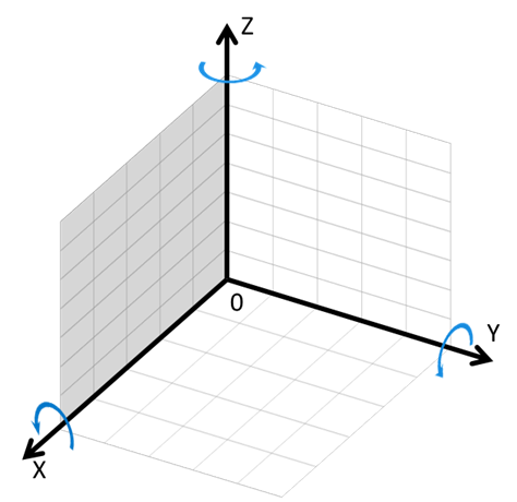
The 3D reference coordinate system outlined below MUST be used for reporting changes in the physical orientation.
Information relating to linear position, velocity and acceleration MUST refer to the zero position on a given axis. Thus a position change or a velocity MUST be positive if moving towards a larger position, measured from the zero position.
\requirement{CC:0031.05.05.11.00C}{0}
Information relating to an angle or change in angle MUST use the right-hand rule. This means that if one (virtually) grabs around an axis with the right hand, with the thumb in the direction of the axis, the angle increases in the direction of the index finger.
Table 2.411 Definition of position, velocity or acceleration
Application
Definition
Linear position, absolute
Position with reference to 0 (e.g. 1 meter)
Linear position, relative
Position with reference to previous position (e.g. 1 meter)
Linear velocity
Position change per time unit (e.g. 1 meter/second)
Linear acceleration
Velocity change per time unit (e.g. 1 meter/second^2)
Polar position, absolute
Angle with reference to 0 (e.g. 45 degrees)
Polar position, relative
Angle with reference to previous angle (e.g. 45 degrees)
Polar velocity (rotation)
Angle change per time unit (e.g. 1 degree/second)
Polar acceleration
Velocity change per time unit (e.g. 1 degree/second^2)
Depending on the number of axes supported by a given device, changes in the physical orientation are mapped to one, two or three axes as outlined in Table 2.412.
Table 2.412 Mapping of 1D, 2D and 3D movement and rotation
Dimensions
Movement
Rotation
1
Along X axis
Around X axis
2
Along X and Y axes
Around X and Y axes
3
Along X, Y and Z axes
Around X, Y and Z axes
A number of Sensor Types allow a device to report changes in the physical orientation.
Table 2.413 Recommended Sensor Types for reporting movement and rotation
Application
Sensor Type
Intended Usage
1D Linear position, absolute
Distance (v3)
Single axis measurement of position (m)
1D Linear position, relative
(no support)
Single axis measurement of position change (m)
1D Linear velocity
Velocity (v2)
Single axis measurement of velocity (m/s)
1D Linear accelleration
Acceleration, X (v8)
Single axis measurement of acceleration (m/s^2)
1D Polar position, absolute
Direction (v2)
Single axis measurement of angle (degrees)
1D Polar position, relative
(no support)
Single axis measurement of angle change
1D Polar velocity
Rotation (v5)
Single axis measurement of velocity (RPM)
1D Polar accelleration
(no support)
Single axis measurement of acceleration (degree/s^2)
2D Linear position, absolute
(no support)
Two axis measurement of position (m)
2D Linear position, relative
(no support)
Two axis measurement of position change (m)
2D Linear velocity
(no support)
Two axis measurement of velocity (m/s)
2D Linear accelleration
Acceleration, X
(v8), Acceleration,
Y (v8)
Two axis measurement of acceleration (m/s^2)
2D Polar position, absolute
(no support)
Two axis measurement of angle (degrees from North)
2D Polar position, relative
(no support)
Two axis measurement of angle change
2D Polar velocity
(no support)
Two axis measurement of velocity (RPM)
2D Polar accelleration
(no support)
Two axis measurement of acceleration (degree/s^2)
3D Linear position, absolute
(no support)
Three axis measurement of position (m)
3D Linear position, relative
(no support)
Three axis measurement of position change (m)
3D Linear velocity
(no support)
Three axis measurement of velocity (m/s)
3D Linear accelleration
Acceleration, X
(v8), Acceleration,
Y (v8), Acceleration,
Z (v8)
Three axis measurement of acceleration (m/s^2)
3D Polar position, absolute
(no support)
Three axis measurement of angle (degrees from North)
3D Polar position, relative
(no support)
Three axis measurement of angle change
3D Polar velocity
(no support)
Three axis measurement of velocity (RPM)
3D Polar accelleration
(no support)
Three axis measurement of acceleration (degree/s^2)
The sensor types “Acceleration, X”, “Acceleration, Y” and “Acceleration, Z” are used to advertise the acceleration of a device along the X, Y and Z axes, respectively.
\requirement{CC:0031.05.05.11.00D}{0}
A one-dimensional device MUST report acceleration using the “Acceleration, X” type.
\requirement{CC:0031.05.05.11.00E}{0}
A two-dimensional device MUST report acceleration using the “Acceleration, X” and “Acceleration, Y” types.
\requirement{CC:0031.05.05.11.00F}{0}
The Scale used MUST be m/s2. An Acceleration value reported with the Scale m/s2 may be converted by a receiving node to a “g-force” level by using the formula below:
1g = 9.81m/s^2
(g represents the unit of Earth Gravity; NOT the weight unit “gram”)
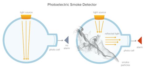
Figure 2.13 shows the principle of how a photoelectric smoke detector works. As shown the smoke sensor uses the smoke to reflect the light onto a photo cell. So when no smoke is present, the light will not be reflected onto the photo cell. When smoke is present, the light will be reflected onto the photo cell. Dependent on the smoke density, more light will be reflected onto the photo cell. So by measuring the received light strength on the photo cell, it is possible to estimate the smoke density.
It is not possible to determine an accurate unit for this, as it is estimated from the light strength on the photo cell. So the exact particle density of the smoke is not known. Also the light strength interval measured on the photo cell, may vary between sensors. So it is decided to report the smoke density in percent, where 0% is no smoke and 100% is the maximum received light strength on the photo cell.
2.2.70.7.3. Detailed description: RF Signal Strength
The RF Signal Strength sensor type may report values using two different scales. While the dBm is a well-defined unit, the RSSI value represents a relative measurement where the internal sampling circuits and the actual sampling method is product specific.
\requirement{CC:0031.05.05.11.010}{0}
The RSSI value MUST be reported in the range 0..100, where the value 100 represents the highest power level that can be measured.