2.2.36. Demand Control Plan Configuration Command Class, version 1
The Demand Control Plan Configuration Command Class allows Utility Suppliers to issue and manage a list of Demand Control Plan (DCP) events to the end consumer.
The DCP Configuration commands are separated for the DCP monitoring commands in the Demand Control Plan Monitor Command Class, allowing the classes to be optionally supported at different security levels. (E.g. DCP monitoring commands could be supported using non-secure communication, while enabling strict secure-only communication for the DCP Configuration Command Class). Refer to the Security and Security 2 command classes for more details.
A DCP event contains information regarding criticality, products involved, requested reduction, time duration and if a certain rate (identified by a Demand Control Plan Rate ID, refer to the Rate Table Configuration Command Class) is associated with the event. When a DCP event is outdated, it is removed from the list. It is the utility supplier responsibility to prevent overflow of the list by query the number of free positions in the list before submitting a new DCP event to the list. Each DCP event is uniquely identified by a timestamp issued the Utility Supplier.
A DCP event may also include information, which enables devices not supporting this class to use in the Demand Control Plan through the Start & Stop Association Group functionality. The installer, the end user or Utility Supplier (remote management) configures the Association groups. During the configuration process the devices are selected and the association entries are created. These associations can additionally be configured with the specific Z-Wave commands (through the Association Command Configuration Command Class). If no Z-Wave commands are specified in the Associations groups, it is the responsibility of the device to issue the relevant commands based on Utility Supplier specific algorithms.
2.2.36.1. DCP list supported get command
This command is used to request the total size of the DCP list along with the number of free entries in the list.
The DCP List Supported Report Command MUST be returned in response to this command.
This command MUST NOT be issued via multicast addressing.
A receiving node MUST NOT return a response if this command is received via multicast addressing. The Z-Wave Multicast frame, the broadcast NodeID and the Multi Channel multi-End Point destination are all considered multicast addressing methods.
7 |
6 |
5 |
4 |
3 |
2 |
1 |
0 |
|---|---|---|---|---|---|---|---|
Command Class = COMMAND_CLASS_DCP_CONFIG (0x3A) |
|||||||
Command = DCP_LIST_SUPPORTED_GET (0x01) |
|||||||
2.2.36.2. DCP list supported report command
This command is used to provide the total size of the DCP list along with the number of free entries in the list.
7 |
6 |
5 |
4 |
3 |
2 |
1 |
0 |
|---|---|---|---|---|---|---|---|
Command Class = COMMAND_CLASS_DCP_CONFIG (0x3A) |
|||||||
Command = DCP_LIST_SUPPORTED_REPORT (0x02) |
|||||||
DCP List Size |
|||||||
Free DCP List entries |
|||||||
DCP List Size (8 bits)
This value specifies the DCP list size. 0x00 is reserved
Free DCP List entries (8 bits)
This value specifics the number of free entries for new DCP events. The value 0x00 specifies a full list.
2.2.36.3. DCP list set command
This command is used to place a new DCP event in the DCP list. Each DCP event is time stamped for future reference.
7 |
6 |
5 |
4 |
3 |
2 |
1 |
0 |
|---|---|---|---|---|---|---|---|
Command Class = COMMAND_CLASS_DCP_CONFIG (0x3A) |
|||||||
Command = DCP_LIST_SET (0x03) |
|||||||
Timestamp -Year 1 |
|||||||
Timestamp -Year 2 |
|||||||
Timestamp -Month |
|||||||
Timestamp -Day |
|||||||
Timestamp -Hour Local Time |
|||||||
Timestamp -Minute Local Time |
|||||||
Timestamp -Second Local Time |
|||||||
DCP Rate ID |
|||||||
Reserved |
Number of DC |
||||||
Generic Device Class 1 |
|||||||
Specific Device Class 1 |
|||||||
… |
|||||||
Generic Device Class N |
|||||||
Specific Device Class N |
|||||||
Start Year 1 |
|||||||
Start Year 2 |
|||||||
Start Month |
|||||||
Start Day |
|||||||
Start Hour Local Time |
|||||||
Start Minute Local Time |
|||||||
Start Second Local Time |
|||||||
Duration Hour Time |
|||||||
Duration Minute Time |
|||||||
Duration Second Time |
|||||||
Event Priority |
|||||||
Load shedding |
|||||||
Start Association Group |
|||||||
Stop Association Group |
|||||||
Randomization interval |
|||||||
Timestamp -Year (16 bits)
Specify the year in the usual Gregorian calendar. The first byte (Year 1) is the most significant byte.
Timestamp -Month (8 bits)
Specify the month of the year between 01 (January) and 12 (December).
Timestamp -Day (8 bits)
Specify the day of the month between 01 and 31.
Timestamp -Hour Local Time (8 bits)
Specify the number of complete hours that have passed since midnight (00-23) in local time.
Timestamp -Minute Local Time (8 bits)
Specify the number of complete minutes that have passed since the start of the hour (00-59) in local time.
Timestamp -Second Local Time (8 bits)
Specify the number of complete seconds since the start of the minute (00-59) in local time. The value 60 used to keep UTC from wandering away is not supported.
DCP Rate ID (8 bits)
Specify if a specific rate is applicable when participating in the DCP event. If an entry in the Rata table contains a matching DCP Rate ID this rate will be active for the duration of the event regardless of other parameters in the rate is not met.
DCP Rate ID usage Example
Prior to the DCP events a given rate table is configured defining when rates are active during a day. The Table contains two entries with DCP Rate IDs allowing the Utility Supplier to activate the rates outside of the time defined in the Table when a DCP event is placed in the DCP list with the corresponding DCP rate ID.
Prior to Jul14 2008 two DCP events are placed in the List by the Utility Supplier, which changes the Rate profile of Jul14 compared to an ‘standard’ day.
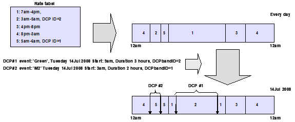
Figure 2.11 DCP Rate ID usage Example
Randomization interval (8 bits)
Specify the randomization interval in units of seconds, which must be applied as an offset to the start and stopping of the events as requested in the DCP event.
E.g. A value of 0x10 specifies that every device should randomly select a start and stop time offset between 0 and 16 seconds. This offset SHOULD be applied to the start and duration fields in the DCP event.
Number of DC (2 bits)
Specify the number of Generic/Specific Device Classes, which are requested to participate in the DCP event
Generic Device Class (8bits)
Specify the Generic Device Class identifier. Refer to [35] and Section 7.
Specific Device Class (8 bits)
Specify the Specific Device Class identifier. Refer to [35] and Section 7.
Start Year (16 bits)
Specify the year in the usual Gregorian calendar for the start of the event. The first byte (Year 1) is the most significant byte.
Start Month (8 bits)
Specify the month of the year between 01 (January) and 12 (December) for the start of the event.
Start Day (8 bits)
Specify the day of the month for the start of the event between 01 and 31.
Start Hour Local Time (8 bits)
Specify the number of complete hours that have passed since midnight (00-23) in local time for the start of the event.
Start Minute Local Time (8 bits)
Specify the number of complete minutes that have passed since the start of the hour (00-59) in local time for the start of the event.
Start Second Local Time (8 bits)
Specify the number of complete seconds since the start of the minute (00-59) in local time. The value 60 used to keep UTC from wandering away is not supported.
Duration Hour Time (8 bits)
Specify the number of complete hours of the event.
Duration Minute Time (8 bits)
Specify the number of complete minutes of the event.
Duration Second Time (8 bits)
Specify the number of complete seconds of the event.
Event Priority (8 bits)
The parameter specifies the priority of the DCP event. The High priority is used by the utility Supplier to mandate device participation and lower priorities are used by devices to voluntary to participate in the event and to which degree.
Event Priority |
Description |
Device participation |
|---|---|---|
0x00 |
Reserved |
Voluntary |
0x01 |
V1 - Green Energy |
Voluntary |
0x02 |
V2 |
Voluntary |
0x03 |
V3 |
Voluntary |
0x04 |
V4 |
Voluntary |
0x05 |
V5 |
Voluntary |
0x06 |
V6 |
Voluntary |
0x07 |
V7 |
Voluntary |
0x08 |
M1 - Emergency |
Mandatory |
0x09 |
M2 |
Mandatory |
0x0A |
M3 |
Mandatory |
0x0B |
M4 |
Mandatory |
0x0C |
Utility defined |
Utility defined |
0x0D |
Utility defined |
Utility defined |
0x0E |
Utility defined |
Utility defined |
0x0F |
Utility defined |
Utility defined |
All other values are reserved and MUST NOT be used by a sending node. Reserved values MUST be ignored by a receiving node.
Load shedding (8 bits)
Specify the load shedding in percentage of average consumption requested for the event. This load shedding will be applied to the devices with the device classes specified in the command.
This field MUST be in the range 0x01..0x64, which represents values in the range 1%..100%. All other values are reserved. Reserved values MUST NOT be used by a sending node and MUST be ignored by a receiving node.
Start Association group (8 bits)
Specify which association group (see the Association Command Class) should be activated when the event is started. The value 0x00 specifies no group should be activated.
If the device also supports the Association Command Configuration Command Class it possible to dynamically and remotely (from the Energy Supplier or others) to specify precisely which current and future Z-Wave commands should be send to which Z-Wave nodes.
The configuration of the Start Association group is done either manually by the installer or automatically when the device detect other relevant devices
Stop Association group (8 bits)
Specify which association group (see the Association Command Class) should be activated when the event is stopped. The value 0x00 specifies no group should be activated.
The configuration of the Stop Association group is done either manually by the installer or automatically when the device detect other relevant devices
Start Associating group and Stop Associating Group usage example
A small energy control system consisting of a device supporting the DCP command class and 3 Z-Wave devices which can participate in the application. NodeId 1: Setback Thermostat device, NodeId 8: Simple Thermostat device, NodeId 5: Multilevel Power Switch device.
Through the use of the Association Command Class and the Association Command Configuration Command Class the following Associations has been established in the device.
Group 1
Node1, Thermostat_Setback_Set(permanent override,energy saving mode)
Node8, Thermostat_Setpoint_Set(Heating setpoint#1, 19,5oC)
Node5, Multilevel_Switch:Set (Dimlevel =0x20)
Group 2
Node1, Thermostat_Setback_Set(No override,Setback = 0oC)
Node8, Thermostat_Setpoint_Set(Heating setpoint#1, 21,5oC)
Node5, Multilevel_Switch:Set (Dimlevel =0x40)
A DCP event can now specifically invoke Group1 when starting the event and invoking group2 when stopping the event by specifying Start Association Group=0x01 and Stop Association Group=0x02.
2.2.36.4. DCP list remove
This command is used to remove a DCP event from the DCP list.
7 |
6 |
5 |
4 |
3 |
2 |
1 |
0 |
|---|---|---|---|---|---|---|---|
Command Class = COMMAND_CLASS_DCP_CONFIG (0x3A) |
|||||||
Command = DCP_LIST_REMOVE (0x04) |
|||||||
Timestamp -Year 1 |
|||||||
Timestamp -Year 2 |
|||||||
Timestamp -Month |
|||||||
Timestamp -Day |
|||||||
Timestamp -Hour Local Time |
|||||||
Timestamp -Minute Local Time |
|||||||
Timestamp -Second Local Time |
|||||||
Refer to DCP list report command for description of fields