2.2.122. Window Covering Command Class, version 1
The Window Covering Command Class is used to control window covering devices.
The Window Covering Command Class is an actuator control command class. Refer to Section 2.1.6.
2.2.122.1. Terminology
A window covering device may be closed or open. The term closed represents the lowest light throughput, while open represents the highest light throughput.
A window covering device may provide one or more properties such as up/down movement combined with for example slats angle control.
Each of the available properties is advertised. A window covering device may offer precise control of the position of a property or it may offer a more limited movement control, where it is possible to start and stop movement in one of two directions but where the target position cannot be specified.
If a window covering parameter is marked as position unknown, this indicates that the actual property can only be controlled via start and stop of movement.
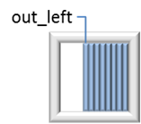
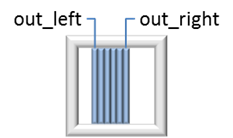
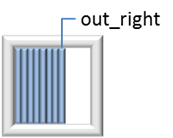
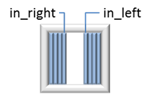
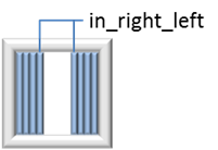
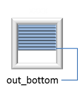
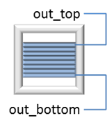
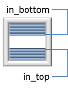
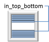
The parameters controlling edges are identified as outlined in Table 2.571.
Edge Title |
Description |
Usage Examples |
|---|---|---|
out_left |
Outbound edge towards the left |
|
out_right |
Outbound edge towards the right |
|
in_left |
Inbound edge towards the left |
|
in_right |
Inbound edge towards the right |
|
in_right_left |
Inbounded edges controlled horizontally as one |
|
out_bottom |
Outbound edge towards the bottom |
|
out_top |
Outbound edge towards the top |
|
in_bottom |
Inbound edge towards the bottom |
|
in_top |
Inbound edge towards the top |
|
in_bottom_top |
Inbound edges controlled vertically as one |
|

2.2.122.2. Compatibility Considerations
This Command Class replaces the following command classes:
Basic Window Covering Command Class [OBSOLETED]
Move To Position Window Covering Command Class [OBSOLETED]
2.2.122.2.1. Motor Control Device Class Support
A node supporting this Command Class SHOULD comply implement the Motor Control Specific Device Class B or C (refer to [35] or Section 7) for backwards compatibility with existing window covering control applications.
2.2.122.2.2. Command Class Dependencies
A node supporting the Window Covering Command Class, Version 1 MUST support the Multilevel Switch Command Class, version 3 or newer.
With the exception for slats angle control, the following mapping MUST apply:
The Multilevel Switch value 0x00 MUST represent the least light, i.e. covering fully closed.
The Multilevel Switch value 0x63 MUST represent the most light, i.e. covering fully opened.
For slats angle control, the following mapping MUST apply:
The Multilevel Switch value 0x00 MUST represent slats closed to the one side.
The Multilevel Switch value 0x32 MUST represent slats open.
The Multilevel Switch value 0x63 MUST represent slats closed to the other side.
By mapping the Multilevel Switch value 0 to the closed position, a multicasted or broadcasted Multilevel Switch Command that turns off light sources will also cause window coverings to close, thus reducing light from the outside.
A supporting node MAY use the Multilevel Switch Command Class to control multiple features like up/down control as well as slats angle control. For instance, the Start Level Change command may start changing the slats angle towards the extreme angle and when reaching that extreme angle, it may start moving up or down.
This way, multiple functions can be controlled from a general purpose remote control, although with less convenience than if a dedicated window covering remote control is used.
2.2.122.3. Window Covering Parameters
Each distinct property of a window covering node is accessed via a dedicated parameter.
Two variants are defined for many parameters: One allows full position control, including movement control. The other variant is limited to movement control.
If a node supports full position control of a property (even parameter IDs), it MUST NOT support the corresonding parameter limited to movement control (odd parameter IDs).
The term “Closed” represents the lowest light throughput, while “Open” represents the highest light throughput of the window covering.
Parm ID |
Description |
Value Range |
Encoding |
|---|---|---|---|
Outbound horizontal control |
|||
0 |
out_left: Outbound edge towards the left Right/Left movement (Position unkonwn) |
N/A |
Level Change Up = Opening Level Change Down = Closing |
1 |
out_left: Outbound edge towards the left Right/Left position Parm 0 MUST NOT be supported |
0x00-0x63 |
0x00 = Closed 0x63 = Open |
2 |
out_right: Outbound edge towards the right Right/Left movement (Position unknown) |
N/A |
Level Change Up = Opening Level Change Down = Closing |
3 |
out_right: Outbound edge towards the right Right/Left position Parm 2 MUST NOT be supported |
0x00-0x63 |
0x00 = Closed 0x63 = Open |
Inbound horizontal control |
|||
4 |
in_left: Inbound edge towards the left Right/Left movement (Position unknown) |
N/A |
Level Change Down = Closing Level Change Up = Opening |
5 |
in_left: Inbound edge towards the left Right/Left position Parm 4 MUST NOT be supported |
0x00-0x63 |
0x00 = Closed 0x63 = Open |
6 |
in_right: Inbound edge towards the right Right/Left movement (Position unknown) |
N/A |
Level Change Down = Closing Level Change Up = Opening |
7 |
in_right: Inbound edge towards the right Right/Left position Parm 6 MUST NOT be supported |
0x00-0x63 |
0x00 = Closed 0x63 = Open |
8 |
in_right_left: Inbound edges controlled horizontally as one Right/Left movement (Position unknown) |
N/A |
Level Change Down = Closing Level Change Down = Opening |
9 |
in_right_left: Inbound edges controlled horizontally as one Right/left position Parm 8 MUST NOT be supported |
0x00-0x63 |
Level Change Down = Closing Level Change Up = Opening |
Angle control of vertical slats |
|||
10 |
Vertical slats angle Right/Left movement (Position unkonwn) |
N/A |
Level Change Down = Closing; to the right inside Level Change Up = Closing; to the left inside (Open is passed midway between the two closing positions) |
11 |
Vertical slats angle Right/Left position Parm 10 MUST NOT be supported |
0x00-0x63 |
0x00 = Closed; to the right inside 0x32 = Open 0x63 = Closed; to the left inside |
Outbound vertical control |
|||
12 |
out_bottom: Outbound edge towards the bottom Up/Down movement (Position unknown) |
N/A |
Level Change Down = Closing Level Change Up = Opening |
13 |
out_bottom: Outbound edge towards the bottom Up/Down position Parm 12 MUST NOT be supported |
0x00-0x63 |
0x00 = Closed 0x63 = Open |
14 |
out_top: Outbound edge towards the top Up/Down movement (Position unknown) |
N/A |
Level Change Down = Closing Level Change Up = Opening |
15 |
out_top: Outbound edge towards the top Up/Down position Parm 14 MUST NOT be supported |
0x00-0x63 |
0x00 = Closed 0x63 = Open |
Inbound vertical control |
|||
16 |
in_bottom: Inbound edge towards the bottom Up/Down movement (Position unknown) |
N/A |
Level Change Down = Closing Level Change Up = Opening |
17 |
in_bottom: Inbound edge towards the bottom |
0x00-0x63 |
0x00 = Closed 0x63 = Open |
18 |
in_top: Inbound edge towards the top Up/Down movement (Position unknown) |
N/A |
Level Change Down = Closing Level Change Up = Opening |
19 |
in_top: Inbound edge towards the top Up/Down position Parm 18 MUST NOT be supported |
0x00-0x63 |
0x00 = Closed 0x63 = Open |
20 |
in_top_bottom: Inbound edges controlled vertically as one Up/Down movement (Position unknown) |
N/A |
Level Change Down = Closing Level Change Up = Opening |
21 |
in_top_bottom: Inbound edges controlled vertically as one Up/Down position Parm 20 MUST NOT be supported |
0x00-0x63 |
0x00 = Closed 0x63 = Open |
Angle control of horizontal slats |
|||
22 |
Horizontal slats angle Up/Down movement (Position unknown) |
N/A |
Level Change Down = Closing; up inside Level Change Up = Closing; down inside (Open is passed midway between the two closing positions) |
23 |
Horizontal slats angle Up/Down position Parm 22 MUST NOT be supported |
0x00-0x63 |
0x00 = Closed; up inside 0x32 = Open 0x63 = Closed; down inside |
All other values are reserved and MUST NOT be used by a sending node. Reserved values MUST be ignored by a receiving node.
A device MAY implement up to 100 hardware levels (including 0) for a given parameter. If a device implements less than 100 hardware levels, the hardware levels MUST be distributed uniformly over the entire range.
The mapping of parameter values to hardware levels MUST be monotonous, i.e. a higher value MUST be mapped to either the same or a higher hardware level. An example is found in Table 2.573.
Horizontal Slats Angle |
Hardware Level |
|---|---|
0x00..0x13 |
100% Up inside |
0x14..0x27 |
50% Up inside |
0x28..0x3B |
Open |
0x3C..0x4F |
50% Down inside |
0x50..0x63 |
100% Down inside |
2.2.122.4. Window Covering Supported Get Command
This command is used to request the supported properties of a device.
The Window Covering Supported Report Command MUST be returned in response to this command.
This command MUST NOT be issued via multicast addressing.
A receiving node MUST NOT return a response if this command is received via multicast addressing. The Z-Wave Multicast frame, the broadcast NodeID and the Multi Channel multi-End Point destination are all considered multicast addressing methods
7 |
6 |
5 |
4 |
3 |
2 |
1 |
0 |
|---|---|---|---|---|---|---|---|
Comand Class = COMMAND_CLASS_WINDOW_COVERING (0x6A) |
|||||||
Command = WINDOW_COVERING_SUPPORTED_GET (0x01) |
|||||||
2.2.122.5. Window Covering Supported Report Command
This command is used to advertise the supported properties of a device.
7 |
6 |
5 |
4 |
3 |
2 |
1 |
0 |
|---|---|---|---|---|---|---|---|
Comand Class = COMMAND_CLASS_WINDOW_COVERING (0x6A) |
|||||||
Command = WINDOW_COVERING_SUPPORTED_REPORT (0x02) |
|||||||
Reserved |
Number of Parameter Mask Bytes |
||||||
Parameter Mask 1 |
|||||||
… |
|||||||
Parameter Mask N |
|||||||
Reserved
This field MUST be set to 0 by a sending node and MUST be ignored by a receiving node.
Number of Parameter Mask bytes (4 bits)
The Number of Parameter Masks field MUST advertise the number of bytes carrying the Covering Parameter Mask field.
The value MUST be in the range 1..15.
Parameter Mask (N Bytes)
The Parameter Mask field MUST advertise the Parameters supported by the device.
The length of this field MUST be advertised by the Number of Parameter Masks field.
Bit 0 in Bit Mask 1 indicates if Parameter ID 0 is supported
Bit 1 in Bit Mask 1 indicates if Parameter ID 1 is supported
…
For the definition of Parameter IDs, refer to Table 2.572.
2.2.122.6. Window Covering Get Command
This command is used to request the status of a specified Covering Parameter.
The Window Covering Report command MUST be returned in response to this command.
This command MUST NOT be issued via multicast addressing.
A receiving node MUST NOT return a response if this command is received via multicast addressing. The Z-Wave Multicast frame, the broadcast NodeID and the Multi Channel multi-End Point destination are all considered multicast addressing methods.
7 |
6 |
5 |
4 |
3 |
2 |
1 |
0 |
|---|---|---|---|---|---|---|---|
Comand Class = COMMAND_CLASS_WINDOW_COVERING (0x6A) |
|||||||
Command = WINDOW_COVERING_GET (0x03) |
|||||||
Parameter ID |
|||||||
Parameter ID (8 bits)
This field MUST specify the Parameter for which the status is requested.
For the definition of Parameter IDs, refer to Table 2.572.
A node receiving an even Parameter ID (marked as “position unknown”) MUST set the Current Value and Target Value fields to 0x00 and the Duration field to 0xFE in the returned Report if the window covering is not moving (i.e., stationary).
2.2.122.7. Window Covering Report Command
This command is used to advertise the status of a Parameter.
7 |
6 |
5 |
4 |
3 |
2 |
1 |
0 |
|---|---|---|---|---|---|---|---|
Comand Class = COMMAND_CLASS_WINDOW_COVERING (0x6A) |
|||||||
Command = WINDOW_COVERING_REPORT (0x04) |
|||||||
Parameter ID |
|||||||
Current Value |
|||||||
Target Value |
|||||||
Duration |
|||||||
Parameter ID (8 bits)
This field MUST advertise the Parameter covered by this report.
For the definition of Parameter IDs, refer to Table 2.572.
Current Value (8 bits)
The Current Value field MUST advertise the current value of the Parameter identified by the Parameter ID field.
The Current Value SHOULD be identical to the Target Value when a transition has ended.
For the definition of valid parameter values, refer to Table 2.572.
Target Value (8 bits)
The Target Value field MUST advertise the target value of an ongoing transition or the most recent transition for the advertised Parameter ID.
If a transition is initiated (i.e., for any Parameter IDs) in an interactive fashion via a local user interface or via a Start Level Change command, the advertised Target Value MUST be 0x00 or 0x63, depending on the direction. If there is not ongoing transation, the Current Value and the Target value field MUST set to 0X00 and Duration field MUST set to 0xFE for an even Parameter IDs.
For the definition of valid parameter values, refer to Table 2.572.
Duration (8 bits)
The Duration field SHOULD advertise the time needed to reach the Target Value at the actual transition rate. The encoding of the Duration field MUST be according to Table 2.10.
The Duration is defined as the interval from start of the transition until the Target Value is reached.
2.2.122.8. Window Covering Set Command
This command is used to control one or more parameters in a window covering device.
7 |
6 |
5 |
4 |
3 |
2 |
1 |
0 |
|---|---|---|---|---|---|---|---|
Comand Class = COMMAND_CLASS_WINDOW_COVERING (0x6A) |
|||||||
Command = WINDOW_COVERING_SET (0x05) |
|||||||
Reserved |
Parameter Count |
||||||
Parameter ID 1 |
|||||||
Value 1 |
|||||||
… |
|||||||
Parameter ID N |
|||||||
Value N |
|||||||
Duration |
|||||||
Reserved
This field MUST be set to 0 by a sending node and MUST be ignored by a receiving node.
Parameter Count (5 bits)
This field MUST specify the number of (Parameter ID, Value) datasets contained in the Window Covering Set command.
Parameter ID (N bytes)
This field MUST specify the Parameter to receive a new value.
A receiving node MUST ignore even Parameters ID (marked as “position unknown”).
For the definition of Parameter IDs, refer to Table 2.572.
Value (N bytes)
This field MUST specify the value of the Parameter identified by the Parameter ID field.
For the definition of valid parameter ID values, refer to Table 2.572.
Duration (8 bits)
The Duration field MUST specify the time that the transition should take from the current value to the new target value.
A supporting device SHOULD respect the specified Duration value.
The encoding of the Duration field MUST be according to Table 2.9.
2.2.122.9. Window Covering Start Level Change Command
This command is used to initiate a transition of one parameter to a new level.
A receiving node MUST initiate the transition to a new value for the specified Parameter ID.
7 |
6 |
5 |
4 |
3 |
2 |
1 |
0 |
|---|---|---|---|---|---|---|---|
Comand Class = COMMAND_CLASS_WINDOW_COVERING (0x6A) |
|||||||
Command = WINDOW_COVERING_START_LEVEL_CHANGE (0x06) |
|||||||
Res |
Up/Down |
Res |
|||||
Parameter ID |
|||||||
Duration |
|||||||
Up/Down (1 bit)
This field MUST specify the direction of the level change.
If the Up/Down bit is set to 0 the level change MUST be increasing.
If the Up/Down bit is set to 1 the level change MUST be decreasing.
Reserved
This field MUST be set to 0 by a sending node and MUST be ignored by a receiving node.
Parameter ID (8 bits)
This field MUST specify the Parameter to start a transition.
A node receiving this command MUST accept all its supported parameter IDs (even and odd).
For the definition of Parameter IDs, refer to Table 2.572.
Duration (8 bits)
The level change rate MUST be calculated to match a level change from the minimum value to the maximum value during the time specified by the Duration field.
A supporting device SHOULD respect the specified Duration value.
The encoding of the Duration field MUST be according to Table 2.9.
2.2.122.10. Window Covering Stop Level Change Command
This command is used to stop an ongoing transition.
7 |
6 |
5 |
4 |
3 |
2 |
1 |
0 |
|---|---|---|---|---|---|---|---|
Comand Class = COMMAND_CLASS_WINDOW_COVERING (0x6A) |
|||||||
Command = WINDOW_COVERING_STOP_LEVEL_CHANGE (0x07) |
|||||||
Parameter ID |
|||||||
Parameter ID (8 bits)
This field MUST specify the parameter to stop a transition.
A receiving node MUST stop the transition if the specified Parameter ID is currently in transition to a new value.
A receiving node MUST NOT stop ongoing transitions for other Parameter IDs than the one specified.
A node receiving this command MUST accept all parameter IDs supported by the device.
For the definition of Parameter IDs, refer to Table 2.572.